.
Plug-in Interpolatie
The Interplation plugin can be used to generate a TIN or IDW interpolation of a point vector layer. It is very simple to handle and provides an intuitive graphical user interface for creating interpolated raster layers (see Figure_interpolation_1). The plugin requires the following parameters to be specified before running:
- Input Vector layers: Specify the input point vector layer(s) from a list of
loaded point layers. If several layers are specified, then data from all layers
is used for interpolation. Note: It is possible to insert lines or polygons as
constraints for the triangulation, by specifying either “points”, “structure
lines” or “break lines” in the Type
 combo box.
 Interpolatie attribuut : Selecteer het attribuut dat moet worden gebruik voor de interpolatie of activeer het keuzevak
 Gebruik Z-coördinaten als de Z-coördinaten moeten worden gebruikt voor de interpolatie.
- Interpolation Method: Select the interpolation method. This can be either ‘Triangulated Irregular Network (TIN)’ or ‘Inverse Distance Weighted (IDW)’. With the TIN method you can create a surface formed by triangles of nearest neighbour points. To do this, circumcircles around selected sample points are created and their intersections are connected to a network of non overlapping and as compact as possible triangles. The resulting surfaces are not smooth. When using the IDW method the sample points are weighted during interpolation such that the influence of one point relative to another declines with distance from the unknown point you want to create. The IDW interpolation method also has some disadvantages: the quality of the interpolation result can decrease, if the distribution of sample data points is uneven. Furthermore, maximum and minimum values in the interpolated surface can only occur at sample data points. This often results in small peaks and pits around the sample data points.
Aantal kolommen/rijen : Specificeer het aantal kolommen en het aantal rijen voor het uitvoerbestand.
Uitvoerbestand: Geef de naam voor het uitvoerbestand op.
- :guidable:`Voeg resultaat toe aan het project` om de uitkomst toe te voegen aan het huidige project.
Note that using lines as constraints for the interpolation the triangulation (TIN method) you can either use ‘structure lines’ or ‘break lines’. When using ‘break lines’ you produce sharp breaks in the surface while using ‘structure lines’ you produce continous breaks. The triangulation is modified by both methods such that no edge crosses a breakline or structure line.
Figure Interpolation 1:
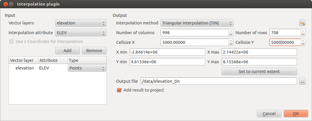
Interpolation Plugin 
Gebruik van de plug-in
- Start QGIS and load a point vector layer (e.g., elevp.csv).
- Load the Interpolation plugin in the Plugin Manager (see
Het dialoogvenster Plug-ins) and click on the Raster ‣ Interpolation ‣
 Interpolation
, which appears in the QGIS menu bar. The Interpolation plugin dialog
appears as shown in Figure_interpolation_1.
Interpolation
, which appears in the QGIS menu bar. The Interpolation plugin dialog
appears as shown in Figure_interpolation_1. - Select an input layer (e.g., elevp ) and column
(e.g., ELEV) for interpolation.
Kies een methode voor de interpolatie (bijv. ‘Triangulated Irregular Network (TIN)’), stel de celgrootte in op 5000 en geef de naam op van het uitvoer rasterbestand (bijv., elevation_tin).
Klik op [OK].