.
Bewerken
QGIS supports various capabilities for editing OGR, SpatiaLite, PostGIS, MSSQL Spatial and Oracle Spatial vector layers and tables.
Notitie
De procedure voor het bewerken van GRASS vectorlagen is anders - zie Digitaliseren en bewerken van een GRASS vectorlaag voor details.
Tip
Tegelijk bewerken
This version of QGIS does not track if somebody else is editing a feature at the same time as you are. The last person to save their edits wins.
Het instellen van de toleranties voor snappen en Zoekradius
Before we can edit vertices, we must set the snapping tolerance and search radius to a value that allows us an optimal editing of the vector layer geometries.
Tolerantie voor ‘snappen’
Snapping tolerance is the distance QGIS uses to search for the closest vertex and/or segment you are trying to connect to when you set a new vertex or move an existing vertex. If you aren’t within the snapping tolerance, QGIS will leave the vertex where you release the mouse button, instead of snapping it to an existing vertex and/or segment. The snapping tolerance setting affects all tools that work with tolerance.
- A general, project-wide snapping tolerance can be defined by choosing
Settings ‣
 Options.
On Mac, go to QGIS ‣
Preferences.... On Linux: Edit ‣
Options. In the Digitizing
tab, you can select between ‘to vertex’, ‘to segment’ or ‘to vertex and segment’
as default snap mode. You can also define a default snapping tolerance and
a search radius for vertex edits. The tolerance can be set either in map
units or in pixels. The advantage of choosing pixels is that the snapping
tolerance doesn’t have to be changed after zoom operations. In our small
digitizing project (working with the Alaska dataset), we define the
snapping units in feet. Your results may vary, but something on the order
of 300 ft at a scale of 1:10000 should be a reasonable
setting.
Options.
On Mac, go to QGIS ‣
Preferences.... On Linux: Edit ‣
Options. In the Digitizing
tab, you can select between ‘to vertex’, ‘to segment’ or ‘to vertex and segment’
as default snap mode. You can also define a default snapping tolerance and
a search radius for vertex edits. The tolerance can be set either in map
units or in pixels. The advantage of choosing pixels is that the snapping
tolerance doesn’t have to be changed after zoom operations. In our small
digitizing project (working with the Alaska dataset), we define the
snapping units in feet. Your results may vary, but something on the order
of 300 ft at a scale of 1:10000 should be a reasonable
setting. - A layer-based snapping tolerance can be defined by choosing Settings ‣ (or File ‣) Snapping options... to enable and adjust snapping mode and tolerance on a layer basis (see figure_edit_1 ).
Note that this layer-based snapping overrides the global snapping option set in the Digitizing tab. So, if you need to edit one layer and snap its vertices to another layer, then enable snapping only on the snap to layer, then decrease the global snapping tolerance to a smaller value. Furthermore, snapping will never occur to a layer that is not checked in the snapping options dialog, regardless of the global snapping tolerance. So be sure to mark the checkbox for those layers that you need to snap to.
Figure Edit 1:
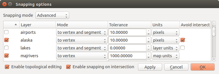
Edit snapping options on a layer basis (Advanced mode) 
The Snapping options enables you to make a quick and simple general setting for all layers in the project so that the pointer snaps to all existing vertices and/or segments when using the ‘All layers’ snapping mode. In most cases it is sufficient to use this snapping mode.
It is important to consider that the per-layer tolerance in ‘map units’ was actually in layer units. So if working with a layer in WGS84 reprojected to UTM, setting tolerance to 1 map unit (i.e. 1 meter) wouldn’t work correctly because the units would be actually degrees. So now the ‘map units’ has been relabeled to ‘layer units’ and the new entry ‘map units’ operates with units of the map view. While working with ‘on-the-fly’ CRS transformation it is now possible to use a snapping tolerance that refers to either the units of the reprojected layer (setting ‘layer units’) or the units of the map view (setting ‘map units’).
Zoekradius
Search radius is the distance QGIS uses to search for the closest vertex you are trying to move when you click on the map. If you aren’t within the search radius, QGIS won’t find and select any vertex for editing, and it will pop up an annoying warning to that effect. Snap tolerance and search radius are set in map units or pixels, so you may find you need to experiment to get them set right. If you specify too big of a tolerance, QGIS may snap to the wrong vertex, especially if you are dealing with a large number of vertices in close proximity. Set search radius too small, and it won’t find anything to move.
The search radius for vertex edits in layer units can be defined in the
Digitizing tab under Settings ‣
Options. This is the same place where you define the general, project-
wide snapping tolerance.
Zooming and Panning
Before editing a layer, you should zoom in to your area of interest. This avoids waiting while all the vertex markers are rendered across the entire layer.
Apart from using the  pan and
  zoom-in /
  zoom-out icons on the toolbar
with the mouse, navigating can also be done with the mouse wheel, spacebar
and the arrow keys.
zoom-out icons on the toolbar
with the mouse, navigating can also be done with the mouse wheel, spacebar
and the arrow keys.
Zooming and panning with the mouse wheel
While digitizing, you can press the mouse wheel to pan inside of the main
window, and you can roll the mouse wheel to zoom in and out on the map.
For zooming, place the mouse cursor inside the map area and roll it forward
(away from you) to zoom in and backwards (towards you) to zoom out. The mouse
cursor position will be the center of the zoomed area of interest. You can
customize the behavior of the mouse wheel zoom using the Map tools
tab under the Settings ‣
Options menu.
Panning with the arrow keys
Panning the map during digitizing is possible with the arrow keys. Place the mouse cursor inside the map area, and click on the right arrow key to pan east, left arrow key to pan west, up arrow key to pan north, and down arrow key to pan south.
You can also use the space bar to temporarily cause mouse movements to pan the map. The PgUp and PgDown keys on your keyboard will cause the map display to zoom in or out without interrupting your digitizing session.
Topologische bewerkingen
Besides layer-based snapping options, you can also define topological
functionalities in the Snapping options... dialog in the
Settings (or File) menu. Here, you can
define  Enable topological editing,
and/or for polygon layers, you can activate the column
Avoid Int., which avoids intersection of new polygons.
Enable topological editing,
and/or for polygon layers, you can activate the column
Avoid Int., which avoids intersection of new polygons.
Topologisch bewerken aanzetten
The option Enable topological editing is for editing
and maintaining common boundaries in polygon mosaics. QGIS ‘detects’ a
shared boundary in a polygon mosaic, so you only have to move the vertex
once, and QGIS will take care of updating the other boundary.
Kruisingen voorkomen
The second topological option in the Avoid Int.
column, called Avoid intersections of new polygons, avoids
overlaps in polygon mosaics. It is for quicker digitizing of adjacent
polygons. If you already have one polygon, it is possible with this option
to digitize the second one such that both intersect, and QGIS then cuts the
second polygon to the common boundary. The advantage is that you don’t
have to digitize all vertices of the common boundary.
Snappen op snijpunten aanzetten
Een andere optie is het keuzevak Snappen op snijpunten aanzetten. Dit geeft de mogelijkheid te ‘snappen’ naar snijpunten van achtergrondlagen, zelfs wanneer er geen hoekpunt aanwezig is op het snijpunt.
Het digitaliseren van een bestaande kaartlaag
By default, QGIS loads layers read-only. This is a safeguard to avoid accidentally editing a layer if there is a slip of the mouse. However, you can choose to edit any layer as long as the data provider supports it, and the underlying data source is writable (i.e., its files are not read-only).
In general, tools for editing vector layers are divided into a digitizing and an advanced digitizing toolbar, described in section Geavanceerd digitaliseren. You can select and unselect both under View ‣ Toolbars ‣. Using the basic digitizing tools, you can perform the following functions:
Pictogram |
Doel |
Pictogram |
Doel |
|---|---|---|---|
 |
Huidige wijzigingen |
 |
Bewerken aan/uitzetten |
 |
Adding Features: Capture Point |  |
Adding Features: Capture Line |
 |
Adding Features: Capture Polygon |  |
Object verplaatsen |
 |
Bewerken van knooppunten |
 |
Geselecteerde verwijderen |
 |
Objecten knippen |
 |
Objecten kopiëren |
 |
Objecten plakken |
 |
Wijzigingen in laag opslaan |
De functies van de werkbalk ‘Digitaliseren’
All editing sessions start by choosing the
Toggle editing option. This can be found in the context menu
after right clicking on the legend entry for a given layer.
Alternatively, you can use the Toggle Editing
Toggle editing button from the digitizing toolbar to start or stop the
editing mode. Once the layer is in edit mode, markers will appear at the
vertices, and additional tool buttons on the editing toolbar will become
available.
Tip
Regelmatig opslaan
Remember to Save Layer Edits regularly. This will also
check that your data source can accept all the changes.
Objecten toevoegen
You can use the Add Feature,
Add Feature or
Add Feature icons on the toolbar to put the QGIS cursor into
digitizing mode.
For each feature, you first digitize the geometry, then enter its attributes. To digitize the geometry, left-click on the map area to create the first point of your new feature.
For lines and polygons, keep on left-clicking for each additional point you wish to capture. When you have finished adding points, right-click anywhere on the map area to confirm you have finished entering the geometry of that feature.
The attribute window will appear, allowing you to enter the information for
the new feature. Figure_edit_2 shows setting attributes for a fictitious new
river in Alaska. In the Digitizing menu under the
Settings ‣ Options menu, you can also activate
Suppress attributes pop-up windows after each created feature and
Reuse last entered attribute values.
Figure Edit 2:
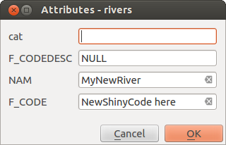
Enter Attribute Values Dialog after digitizing a new vector
feature
With the Move Feature(s) icon on the toolbar, you can
move existing features.
Tip
Attribute Value Types
For editing, the attribute types are validated during entry. Because of this, it is not possible to enter a number into a text column in the dialog Enter Attribute Values or vice versa. If you need to do so, you should edit the attributes in a second step within the Attribute table dialog.
Current Edits
This feature allows the digitization of multiple layers. Choose
 Save for Selected Layers to save all changes you
made in multiple layers. You also have the opportunity to
Save for Selected Layers to save all changes you
made in multiple layers. You also have the opportunity to
 Rollback for Selected Layers, so that the
digitization may be withdrawn for all selected layers.
If you want to stop editing the selected layers,
Rollback for Selected Layers, so that the
digitization may be withdrawn for all selected layers.
If you want to stop editing the selected layers,  Cancel for Selected Layer(s)
is an easy way.
Cancel for Selected Layer(s)
is an easy way.
Dezelfde functionaliteit is beschikbaar voor het bewerken van alle lagen.
Bewerken van knooppunten
For shapefile-based layers as well as SpatialLite, PostgreSQL/PostGIS, MSSQL Spatial, and Oracle Spatial tables, the
Node Tool provides manipulation capabilities of
feature vertices similar to CAD programs. It is possible to simply select
multiple vertices at once and to move, add or delete them altogether.
The node tool also works with ‘on the fly’ projection turned on, and it supports
the topological editing feature. This tool is, unlike other tools in
QGIS, persistent, so when some operation is done, selection stays
active for this feature and tool. If the node tool is unable to find any
features, a warning will be displayed.
It is important to set the property Settings ‣
Options ‣ Digitizing ‣ Search Radius:
 to a number greater than zero (i.e., 10). Otherwise, QGIS will
not be able to tell which vertex is being edited.
to a number greater than zero (i.e., 10). Otherwise, QGIS will
not be able to tell which vertex is being edited.
Tip
Knooppunt markeringen
The current version of QGIS supports three kinds of vertex markers:
‘Semi-transparent circle’, ‘Cross’ and ‘None’. To change the marker style,
choose Options from the
Settings menu, click on the Digitizing
tab and select the appropriate entry.
Standaard bewerkingen
Start by activating the Node Tool and selecting a
feature by clicking on it. Red boxes will appear at each vertex of this feature.
- Selecting vertices: You can select vertices by clicking on them one at a time, by clicking on an edge to select the vertices at both ends, or by clicking and dragging a rectangle around some vertices. When a vertex is selected, its color changes to blue. To add more vertices to the current selection, hold down the Ctrl key while clicking. Hold down Ctrl or Shift when clicking to toggle the selection state of vertices (vertices that are currently unselected will be selected as usual, but also vertices that are already selected will become unselected).
Toevoegen van knooppunten: Om een knooppunt toe te voegen kunt u dichtbij of op een lijnstuk klikken. Het nieuwe knooppunt zal overigens altijd toegevoegd worden op de bestaande lijn en niet op de plaats waar u met de muis hebt geklikt. Het nieuwe knooppunt kunt u, indien nodig, daarna verplaatsen.
- Deleting vertices: After selecting vertices for deletion, click the
Delete key. Note that you cannot use the
Node Tool to delete a complete feature; QGIS will ensure it retains
the minimum number of vertices for the feature type you are working on.
To delete a complete feature use the
Delete Selected tool.
- Moving vertices: Select all the vertices you want to move. Click on a selected vertex or edge and drag in the direction you wish to move. All the selected vertices will move together. If snapping is enabled, the whole selection can jump to the nearest vertex or line.
Each change made with the node tool is stored as a separate entry in the Undo dialog. Remember that all operations support topological editing when this is turned on. On-the-fly projection is also supported, and the node tool provides tooltips to identify a vertex by hovering the pointer over it.
Objecten knippen, kopiëren en plakken
Selected features can be cut, copied and pasted between layers in the same
QGIS project, as long as destination layers are set to
Toggle editing beforehand.
Features can also be pasted to external applications as text. That is, the features are represented in CSV format, with the geometry data appearing in the OGC Well-Known Text (WKT) format.
However, in this version of QGIS, text features from outside QGIS cannot be pasted to a layer within QGIS. When would the copy and paste function come in handy? Well, it turns out that you can edit more than one layer at a time and copy/paste features between layers. Why would we want to do this? Say we need to do some work on a new layer but only need one or two lakes, not the 5,000 on our big_lakes layer. We can create a new layer and use copy/paste to plop the needed lakes into it.
Als voorbeeld zullen we enkele lagen van de laag met meren kopiëren naar een nieuwe laag:
Laad de laag van waaruit u objecten wilt kopiëren (de bronlaag)
Laad of maak de laag aan waar je naartoe wilt kopiëren (de doellaag)
Zet het bewerken aan voor de doellaag
Maak de bronlaag de actieve laag door deze te selecteren in de legenda
- Use the
 Select Single Feature tool to select the
feature(s) on the source layer
Select Single Feature tool to select the
feature(s) on the source layer - Click on the Copy Features tool
Maak nu de doellaag de actieve laag door er op te klikken in de legenda
- Click on the Paste Features tool
Zet bewerken voor de laag uit en sla de wijzigingen op
What happens if the source and target layers have different schemas (field names and types are not the same)? QGIS populates what matches and ignores the rest. If you don’t care about the attributes being copied to the target layer, it doesn’t matter how you design the fields and data types. If you want to make sure everything - the feature and its attributes - gets copied, make sure the schemas match.
Tip
Behoud van eigenschappen geplakte objecten
If your source and destination layers use the same projection, then the pasted features will have geometry identical to the source layer. However, if the destination layer is a different projection, then QGIS cannot guarantee the geometry is identical. This is simply because there are small rounding-off errors involved when converting between projections.
Tip
tekenreeks van attribuut naar een ander kopiëren
If you have created a new column in your attribute table with type ‘string’ and want to paste values from another attribute column that has a greater length the length of the column size will be extended to the same amount. This is because the GDAL Shapefile driver starting with GDAL/OGR 1.10 knows to auto-extend string and integer fields to dynamically accomodate for the length of the data to be inserted.
Geselecteerde objecten verwijderen
If we want to delete an entire polygon, we can do that by first selecting the
polygon using the regular Select Single Feature tool. You
can select multiple features for deletion. Once you have the selection set,
use the Delete Selected tool to delete the
features.
The Cut Features tool on the digitizing toolbar can
also be used to delete features. This effectively deletes the feature but
also places it on a “spatial clipboard”. So, we cut the feature to delete.
We could then use the Paste Features tool to put it back,
giving us a one-level undo capability. Cut, copy, and paste work on the
currently selected features, meaning we can operate on more than one at a time.
Bewerkte lagen opslaan
When a layer is in editing mode, any changes remain in the memory of QGIS.
Therefore, they are not committed/saved immediately to the data source or disk.
If you want to save edits to the current layer but want to continue editing
without leaving the editing mode, you can click the
Save Layer Edits button. When you turn editing mode off with
Toggle editing (or quit QGIS for that matter),
you are also asked if you want to save your changes or discard them.
If the changes cannot be saved (e.g., disk full, or the attributes have values that are out of range), the QGIS in-memory state is preserved. This allows you to adjust your edits and try again.
Tip
Integriteit van gegevens
It is always a good idea to back up your data source before you start editing. While the authors of QGIS have made every effort to preserve the integrity of your data, we offer no warranty in this regard.
Geavanceerd digitaliseren
Pictogram |
Doel |
Pictogram |
Doel |
|---|---|---|---|
 |
Ongedaan maken |
 |
Opnieuw |
 |
Object(en) roteren |
 |
Object vereenvoudigen |
 |
Ring toevoegen |
 |
Onderdeel toevoegen |
 |
Ring vullen |
 |
Verwijder ring |
 |
Onderdeel verwijderen |
 |
Object vervormen |
 |
Verspring curve |
 |
Kaartobjecten splitsen |
 |
Delen splitsen |
 |
Geselecteerde objecten samenvoegen |
 |
Attributen van geselecteerde objecten samenvoegen |
 |
Puntsymbolen roteren |
Tabel Geavanceerd bewerken: De werkbalk Geavanceerd digitaliseren voor vectorlagen
Ongedaan maken en Opnieuw
The Undo and Redo tools allows you
to undo or redo vector editing operations. There is also a dockable
widget, which shows all operations in the undo/redo history (see
Figure_edit_3). This widget is not displayed by default; it can be
displayed by right clicking on the toolbar and activating the Undo/Redo
checkbox. Undo/Redo is however active, even if the widget is not displayed.
Figure Edit 3:
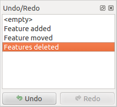
Redo and Undo digitizing steps
When Undo is hit, the state of all features and attributes are reverted to the state before the reverted operation happened. Changes other than normal vector editing operations (for example, changes done by a plugin), may or may not be reverted, depending on how the changes were performed.
Met het panel Ongedaan maken/Opnieuw kun je door te klikken op een bewerking in de lijst direct naar de situatie terugspringen van voor de bewerking.
Object(en) roteren
Use Rotate Feature(s) to rotate one or multiple features
in the map canvas. Press the Rotate Feature(s) icon and then
click on the feature to rotate. Either click on the map to place the rotated feature or
enter an angle in the user input widget. If you want to rotate several features,
they shall be selected first.
Als u het kaartgereedschap inschakelt met geselecteerd(e) object(en), verschijnen hun zwaartepunten en die zullen het ankerpunt voor de rotatie zijn. Indien u het ankerpunt wilt verplaatsen, houd de Ctrl-toets ingedrukt en klik op de kaart om het te plaatsen.
Indien u Shift ingedrukt houdt vóór het klikken op de kaart, wordt het roteren uitgevoerd in stappen van 45 graden, die later kunnen worden aangepast in de widget voor invoer door de gebruiker.
Object vereenvoudigen
The Simplify Feature tool allows you to reduce the
number of vertices of a feature, as long as the geometry doesn’t change. With the
tool you can also simplify multi-part features.
First, drag a rectangle over the feature. The vertices will be highlighted in red while the color of the
feature will change and a dialog where you can define a tolerance in map units or pixels
will appear. QGIS calculates the amount of vertices that can be deleted while maintaining the
geometry using the given tolerance. The higher the tolerance is the more vertices can be deleted. After
gaining the statistics about the simplification just klick the OK button.
The tolerance you used will be saved when leaving a project or when leaving an edit session.
So you can go back to the same tolerance the next time when simplifying a feature.
Ring toevoegen
You can create ring polygons using the
Add Ring icon in the toolbar. This means that inside an existing area, it
is possible to digitize further polygons that will occur as a ‘hole’, so
only the area between the boundaries of the outer and inner polygons remains
as a ring polygon.
Onderdeel toevoegen
You can add part polygons to a selected
multipolygon. The new part polygon must be digitized outside
the selected multi-polygon.
Ring vullen
You can use the Fill Ring function to add a ring to
a polygon and add a new feature to the layer at the same time. Thus you need not
first use the Add Ring icon and then the
Add feature function anymore.
Verwijder ring
The Delete Ring tool allows you to delete ring polygons
inside an existing area. This tool only works with polygon layers. It doesn’t
change anything when it is used on the outer ring of the polygon. This tool
can be used on polygon and multi-polygon features. Before you select the
vertices of a ring, adjust the vertex edit tolerance.
Onderdeel verwijderen
The Delete Part tool allows you to delete parts from
multifeatures (e.g., to delete polygons from a multi-polygon feature). It won’t
delete the last part of the feature; this last part will stay untouched. This
tool works with all multi-part geometries: point, line and polygon. Before you
select the vertices of a part, adjust the vertex edit tolerance.
Object vervormen
You can reshape line and polygon features using the
Reshape Features icon on the toolbar. It replaces the line or polygon
part from the first to the last intersection with the original line. With
polygons, this can sometimes lead to unintended results. It is mainly useful
to replace smaller parts of a polygon, not for major overhauls, and the reshape
line is not allowed to cross several polygon rings, as this would generate an
invalid polygon.
U kunt, bijvoorbeeld, de grens van een polygoon bewerken met dit gereedschap. Klik eerst aan de binnenkant van de polygoon vlakbij het punt waar de nieuwe grens moet beginnen, steek daar de grens van de polygoon over en begin dan met het tekenen van de nieuwe grens buiten de huidige grens van de polygoon. Eindig het toevoegen van nieuwe grenspunten door het laatste punt aan de binnenkant van de huidige grens te plaatsen met de rechter muisknop. Op de snijpunten van de nieuwe met de oude grens zullen door deze functie automatisch nieuwe punten worden toegevoegd. De polygoon kan ook kleiner worden gemaakt door buiten de huidige grens te beginnen en binnen de huidige grens van de polygoon de nieuwe grens te tekenen en met klikken van de rechter muisknop het tekenen te stoppen buiten de huidige grens.
Notitie
Het gereedschap Objecten vervormen kan het startpunt van een polygoon of een gesloten lijn wijzigen. Dus het punt dat twee keer voorkomt kan een ander punt zijn. Dit zal geen probleem zijn voor de meeste applicaties, maar hier dient wel rekening mee worden gehouden.
Verspring curve
The Offset Curve tool creates parallel shifts of line layers.
The tool can be applied to the edited layer (the geometries are modified)
or also to background layers (in which case it creates copies of the lines / rings and adds them to the the edited layer).
It is thus ideally suited for the creation of distance line layers. The displacement is
shown at the bottom left of the taskbar.
To create a shift of a line layer, you must first go into editing mode and activate the
Offset Curve tool. Then click on a feature to shift it.
Move the mouse and click where wanted or enter the desired distance in the user input widget. Your changes may then be saved with the|mActionSaveEdits|:sup:Save Layer Edits tool.
QGIS options dialog (Digitizing tab then Curve offset tools section) allows you to configure some parameters like Join style, Quadrant segments, Miter limit.
Kaartobjecten splitsen
You can split features using the Split Features
icon on the toolbar. Just draw a line across the feature you want to split.
Delen splitsen
In QGIS 2.0 it is now possible to split the parts of a multi part feature so that the
number of parts is increased. Just draw a line across the part you want to split using
the Split Parts icon.
Geselecteerde objecten samenvoegen
The Merge Selected Features tool allows you to merge
features. A new dialog will allow you to choose which value to choose between each
selected features or select a function (Minimum, Maximum, Median, Sum, Skip
Attribute) to use for each column. If features don’t have a common boundaries,
a multipolygon will be created.
Samenvoegen attribuutwaarden van geselecteerde objecten
The Merge Attributes of Selected Features tool
allows you to merge attributes of features with common boundaries and
attributes without merging their boundaries.
First, select several features at once. Then
press the Merge Attributes of Selected Features button.
Now QGIS asks you which attributes are to be applied to all selected objects.
As a result, all selected objects have the same attribute entries.
Puntsymbolen roteren
Rotate Point Symbols allows you to change the rotation
of point symbols in the map canvas. You must first define a rotation column
from the attribute table of the point layer in the Advanced menu of the
Style menu of the Layer Properties. Also, you will need to
go into the ‘SVG marker’ and choose Data defined properties ....
Activate Angle and choose ‘rotation’ as field.
Without these settings, the tool is inactive.
Figure Edit 4:
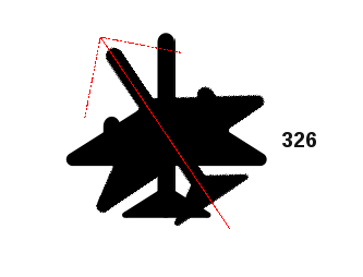
Rotate Point Symbols
To change the rotation, select a point feature in the map canvas and rotate it, holding the left mouse button pressed. A red arrow with the rotation value will be visualized (see Figure_edit_4). When you release the left mouse button again, the value will be updated in the attribute table.
Notitie
Wanneer de Ctrl-toets ingedrukt wordt gehouden, zal het roteren worden uitgevoerd in stappen van 15 graden.
Het paneel Geavanceerd digitaliseren
When capturing new geometries or geometry parts you also have the possibility to use the Advanced Digitizing panel. You can digitize lines exactly parallel or at a specific angle or lock lines to specific angles. Furthermore you can enter coordinates directly so that you can make a precise definition for your new geomtry.
_figure_advanced_edit 1:
Figure Advanced Edit 1:
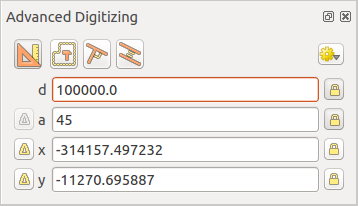
The Advanced Digitizing panel
De gereedschappen zijn niet ingeschakeld als de kaartweergave in geografische coördinaten is.
Nieuwe vectorlagen maken
QGIS allows you to create new shapefile layers, new SpatiaLite layers, new GPX layers and New Temporary Scratch Layers. Creation of a new GRASS layer is supported within the GRASS plugin. Please refer to section Maken van een nieuwe GRASS vectorlaag for more information on creating GRASS vector layers.
Nieuwe Shapefile-laag maken
To create a new shape layer for editing, choose New ‣
 New Shapefile Layer... from the
Layer menu. The New Vector Layer dialog will be
displayed as shown in Figure_edit_5. Choose the type of layer (point, line or
polygon) and the CRS (coordinate reference system).
New Shapefile Layer... from the
Layer menu. The New Vector Layer dialog will be
displayed as shown in Figure_edit_5. Choose the type of layer (point, line or
polygon) and the CRS (coordinate reference system).
Note that QGIS does not yet support creation of 2.5D features (i.e., features with X,Y,Z coordinates).
Figure Edit 5:
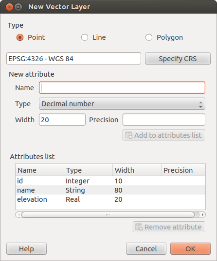
Creating a new Shapefile layer Dialog
To complete the creation of the new shapefile layer, add the desired attributes
by clicking on the [Add to attributes list] button and specifying a name and type for the
attribute. A first ‘id’ column is added as default but can be removed, if not
wanted. Only Type: real  , Type: integer
, Type: string and Type:date
attributes are supported. Additionally and according to the attribute type, you can also define
the width and precision of the new attribute column. Once you are happy with
the attributes, click [OK] and provide a name for the shapefile. QGIS will
automatically add a .shp extension to the name you specify. Once the
layer has been created, it will be added to the map, and you can edit it in the
same way as described in section Het digitaliseren van een bestaande kaartlaag above.
, Type: integer
, Type: string and Type:date
attributes are supported. Additionally and according to the attribute type, you can also define
the width and precision of the new attribute column. Once you are happy with
the attributes, click [OK] and provide a name for the shapefile. QGIS will
automatically add a .shp extension to the name you specify. Once the
layer has been created, it will be added to the map, and you can edit it in the
same way as described in section Het digitaliseren van een bestaande kaartlaag above.
Nieuwe Spatialite-laag maken
To create a new SpatiaLite layer for editing, choose New ‣
 New SpatiaLite Layer... from the
Layer menu. The New SpatiaLite Layer dialog will
be displayed as shown in Figure_edit_6.
New SpatiaLite Layer... from the
Layer menu. The New SpatiaLite Layer dialog will
be displayed as shown in Figure_edit_6.
Figure Edit 6:
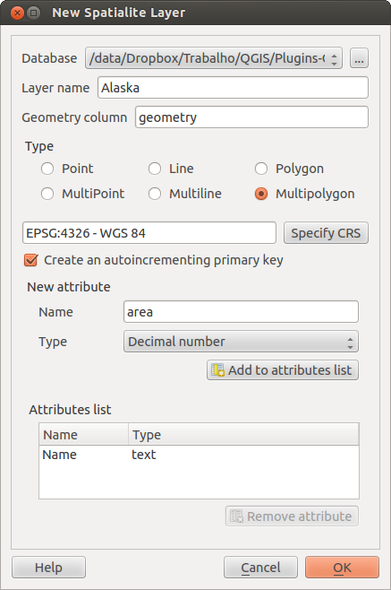
Creating a New SpatiaLite layer Dialog
The first step is to select an existing SpatiaLite database or to create a new
SpatiaLite database. This can be done with the browse button  to
the right of the database field. Then, add a name for the new layer, define
the layer type, and specify the coordinate reference system with [Specify CRS].
If desired, you can select Create an autoincrementing primary key.
to
the right of the database field. Then, add a name for the new layer, define
the layer type, and specify the coordinate reference system with [Specify CRS].
If desired, you can select Create an autoincrementing primary key.
To define an attribute table for the new SpatiaLite layer, add the names of the attribute columns you want to create with the corresponding column type, and click on the [Add to attribute list] button. Once you are happy with the attributes, click [OK]. QGIS will automatically add the new layer to the legend, and you can edit it in the same way as described in section Het digitaliseren van een bestaande kaartlaag above.
De DB Manager kan gebruikt worden voor overig beheer van SpatiaLite lagen, zie Plug-in DB Manager.
Een nieuwe GPX-laag maken
To create a new GPX file, you need to load the GPS plugin first. Plugins ‣
 Plugin Manager... opens the Plugin Manager Dialog.
Activate the GPS Tools checkbox.
Plugin Manager... opens the Plugin Manager Dialog.
Activate the GPS Tools checkbox.
When this plugin is loaded, choose New ‣  Create new GPX Layer... from the Layer menu.
In the Save new GPX file as dialog, you can choose where to save the
new GPX layer.
Create new GPX Layer... from the Layer menu.
In the Save new GPX file as dialog, you can choose where to save the
new GPX layer.
Een nieuwe tijdelijke tekenlaag maken
Empty, editable memory layers can be defined using Layer ‣ Create Layer ‣ New Temporary Scratch Layer.
Here you can even create  Multipoint, Multiline
and Multipolygon Layers beneath
Multipoint, Multiline
and Multipolygon Layers beneath  Point,
Line and Polygon Layers.
Temporary Scratch Layers are not saved and will be discarded when QGIS is closed.
See also paste_into_layer .
Point,
Line and Polygon Layers.
Temporary Scratch Layers are not saved and will be discarded when QGIS is closed.
See also paste_into_layer .
Working with the Attribute Table
The attribute table displays features of a selected layer. Each row in the table represents one map feature, and each column contains a particular piece of information about the feature. Features in the table can be searched, selected, moved or even edited.
To open the attribute table for a vector layer, make the layer active by
clicking on it in the map legend area. Then, from the main
Layer menu, choose  Open Attribute
Table. It is also possible to right click on the layer and choose
Open Attribute Table from the drop-down menu,
and to click on the Open Attribute Table button
in the Attributes toolbar.
Open Attribute
Table. It is also possible to right click on the layer and choose
Open Attribute Table from the drop-down menu,
and to click on the Open Attribute Table button
in the Attributes toolbar.
This will open a new window that displays the feature attributes for the layer (figure_attributes_1). The number of features and the number of selected features are shown in the attribute table title.
Figure Attributes 1:
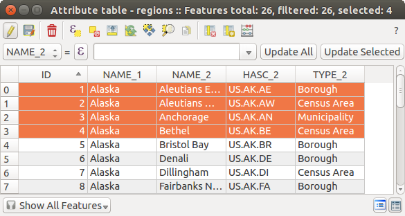
Attribute Table for regions layer
Selecting features in an attribute table
Each selected row in the attribute table displays the attributes of a selected feature in the layer. If the set of features selected in the main window is changed, the selection is also updated in the attribute table. Likewise, if the set of rows selected in the attribute table is changed, the set of features selected in the main window will be updated.
Rows can be selected by clicking on the row number on the left side of the row. Multiple rows can be marked by holding the Ctrl key. A continuous selection can be made by holding the Shift key and clicking on several row headers on the left side of the rows. All rows between the current cursor position and the clicked row are selected. Moving the cursor position in the attribute table, by clicking a cell in the table, does not change the row selection. Changing the selection in the main canvas does not move the cursor position in the attribute table.
The table can be sorted by any column, by clicking on the column header. A small arrow indicates the sort order (downward pointing means descending values from the top row down, upward pointing means ascending values from the top row down).
For a simple search by attributes on only one column, choose the Column filter ‣ from the menu in the bottom left corner. Select the field (column) on which the search should be performed from the drop-down menu, and hit the [Apply] button. Then, only the matching features are shown in the attribute table.
To make a selection, you have to use the  Select features using an Expression
icon on top of the attribute table.
Select features using an Expression allows you
to define a subset of a table using a Function List like in the
Select features using an Expression
icon on top of the attribute table.
Select features using an Expression allows you
to define a subset of a table using a Function List like in the
 Field Calculator (see Veldberekening).
The query result can then be saved as a new vector layer.
For example, if you want to find regions that are boroughs from regions.shp
of the QGIS sample data, you have to open the Fields and Values menu
and choose the field that you want to query. Double-click the field ‘TYPE_2’ and also
[Load all unique values] . From the list, choose and double-click ‘Borough’.
In the Expression field, the following query appears:
Field Calculator (see Veldberekening).
The query result can then be saved as a new vector layer.
For example, if you want to find regions that are boroughs from regions.shp
of the QGIS sample data, you have to open the Fields and Values menu
and choose the field that you want to query. Double-click the field ‘TYPE_2’ and also
[Load all unique values] . From the list, choose and double-click ‘Borough’.
In the Expression field, the following query appears:
"TYPE_2" = 'Borough'
Here you can also use the Function list ‣ Recent (Selection) to make a selection that you used before. The expression builder remembers the last 20 used expressions.
The matching rows will be selected, and the total number of matching rows will appear in the title bar of the attribute table, as well as in the status bar of the main window. For searches that display only selected features on the map, use the Query Builder described in section Querybouwer.
To show selected records only, use Show Selected Features from the menu at the bottom left.
The field calculator bar allows you to make calculations on the selected rows only. For example, you can alter the number of the ID field of the file:regions.shp with the expression
ID+5
as shown in figure_attributes_1 .
The other buttons at the top of the attribute table window provide the following functionality:
- Toggle editing mode to edit single values
and to enable functionalities described below (also with Ctrl+E)
- Save Edits (also with Ctrl+S)
 Unselect all (also with Ctrl+U)
 Move selected to top (also with Ctrl+T)
 Invert selection (also with Ctrl+R)
 Copy selected rows to clipboard (also with
Ctrl+C)
Copy selected rows to clipboard (also with
Ctrl+C) Zoom map to the selected rows (also with
Ctrl+J)
Zoom map to the selected rows (also with
Ctrl+J) Pan map to the selected rows (also with Ctrl+P)
- Delete selected features (also with
Ctrl+D)
 New Column for PostGIS layers and for OGR
layers with GDAL version >= 1.6 (also with Ctrl+W)
New Column for PostGIS layers and for OGR
layers with GDAL version >= 1.6 (also with Ctrl+W) Delete Column for PostGIS layers and for OGR
layers with GDAL version >= 1.9 (also with Ctrl+L)
Delete Column for PostGIS layers and for OGR
layers with GDAL version >= 1.9 (also with Ctrl+L)- Open field calculator (also with Ctrl+I)
Below these buttons is the Field Calculator bar, which allows calculations
to be quickly applied attributes visible in the table. This bar uses the
same expressions as the Field Calculator
(see Veldberekening).
Tip
Skip WKT geometry
If you want to use attribute data in external programs (such as Excel), use the
Copy selected rows to clipboard button.
You can copy the information without vector geometries if you deactivate
Settings ‣ Options ‣ Data sources menu
Copy geometry in WKT representation from attribute table.
Save selected features as new layer
The selected features can be saved as any OGR-supported vector format and
also transformed into another coordinate reference system (CRS). Just open
the right mouse menu of the layer and click on Save
as to define the name of the output file, its format and CRS (see section
Map Legend). To save the selection ensure that the
Save only selected features is selected.
It is also possible to specify OGR creation options within the dialog.
Paste into new layer
Features that are on the clipboard may be pasted into a new layer. To do this, first make a layer editable. Select some features, copy them to the clipboard, and then paste them into a new layer using Edit ‣ Paste Features as and choosing New vector layer or New memory layer.
This applies to features selected and copied within QGIS and also to features from another source defined using well-known text (WKT).
Working with non spatial attribute tables
QGIS allows you also to load non-spatial tables. This currently includes tables
supported by OGR and delimited text, as well as the PostgreSQL, MSSQL and Oracle provider.
The tables can be used for field lookups or just generally browsed and edited using the table
view. When you load the table, you will see it in the legend field. It can be
opened with the Open Attribute Table tool and
is then editable like any other layer attribute table.
As an example, you can use columns of the non-spatial table to define attribute values, or a range of values that are allowed, to be added to a specific vector layer during digitizing. Have a closer look at the edit widget in section Menu Velden to find out more.
Creating one to many relations
Relations are a technique often used in databases. The concept is, that features (rows) of different layers (tables) can belong to each other.
As an example you have a layer with all regions of alaska (polygon) which provides some attributes about its name and region type and a unique id (which acts as primary key).
Foreign keys
Then you get another point layer or table with information about airports that are located in the regions and you also want to keep track of these. If you want to add them to the region layer, you need to create a one to many relation using foreign keys, because there are several airports in most regions.
Figure Relations 1:
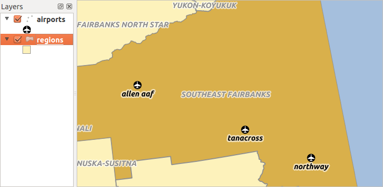
Alaska region with airports
In addition to the already existing attributes in the airports attribute table another field fk_region which acts as a foreign key (if you have a database, you will probably want to define a constraint on it).
This field fk_region will always contain an id of a region. It can be seen like a pointer to the region it belongs to. And you can design a custom edit form for the editing and QGIS takes care about the setup. It works with different providers (so you can also use it with shape and csv files) and all you have to do is to tell QGIS the relations between your tables.
Layers
QGIS makes no difference between a table and a vector layer. Basically, a vector layer is a table with a geometry. So can add your table as a vector layer. To demostrate you can load the ‘region’ shapefile (with geometries) and the ‘airport’ csv table (without geometries) and a foreign key (fk_region) to the layer region. This means, that each airport belongs to exactly one region while each region can have any number of airports (a typical one to many relation).
Definition (Relation Manager)
The first thing we are going to do is to let QGIS know about the relations between the layer. This is done in Settings ‣ Project Properties. Open the Relations menu and click on Add.
- name is going to be used as a title. It should be a human readable string, describing, what the relation is used for. We will just call say “Airports” in this case.
- referencing layer is the one with the foreign key field on it. In our case this is the airports layer
- referencing field will say, which field points to the other layer so this is fk_region in this case
- referenced layer is the one with the primary key, pointed to, so here it is the regions layer
- referenced field is the primary key of the referenced layer so it is ID
- id will be used for internal purposes and has to be unique. You may need it to build custom forms once this is supported. If you leave it empty, one will be generated for you but you can assign one yourself to get one that is easier to handle.
Figure Relations 2:
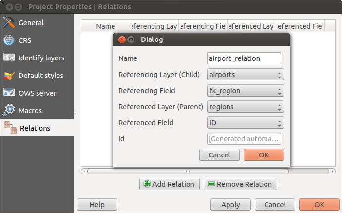
Relation Manager
Forms
Now that QGIS knows about the relation, it will be used to improve the forms it generates. As we did not change the default form method (autogenerated) it will just add a new widget in our form. So let’s select the layer region in the legend and use the identify tool. Depending on your settings, the form might open directly or you will have to choose to open it in the identification dialog under actions.
Figure Relations 3:
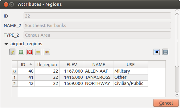
Identification dialog regions with relation to airports
As you can see, the airports assigned to this particular region are all shown in a table. And there are also some buttons available. Let’s review them shortly
- The button is for toggling the edit mode. Be aware that it toggles the edit mode of the airport layer, although we are in the feature form of a feature from the region layer. But the table is representing features of the airport layer.
- The
 button will add a new feature to the airport layer. And it will assign the new airport to the current region by default.
 - The
 button will delete the selected airport permanently.
 - The
 symbol will open a new dialog where you can select any existing airport which will then be assigned to the current region. This may be handy if you created the airport on the wrong region by accident.
 - The
 symbol will unlink the selected airport from the current region, leaving them unassigned (the foreign key is set to NULL) effectively.
 - The two buttons to the right switch between table view and form view where the later let’s you view all the airports in their respective form.
If you work on the airport table, a new widget type is available which lets you embed the feature form of the referenced region on the feature form of the airports. It can be used when you open the layer properties of the airports table, switch to the Fields menu and change the widget type of the foreign key field ‘fk_region’ to Relation Reference.
If you look at the feature dialog now, you will see, that the form of the region is embedded inside the airports form and will even have a combobox, which allows you to assign the current airport to another region.
Figure Relations 4:
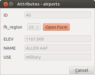
Identification dialog airport with relation to regions