.
編集
QGIS は OGR, SpatiaLite, PostGIS, MSSQL SpatialやOracle Spatial vector とテーブルに対する様々な 編集 機能をサポートしています.
ノート
GRASSレイヤを編集する手順は異なります- 詳細は GRASSベクタレイヤのデジタイジングと編集 のセクションを参照ください。
ちなみに
同時編集
QGIS のバージョンは誰があなたと一緒に地物の同時編集を行なっているかは追跡しません.最後に保存した人の編集結果が残ります.
スナップ許容量と検索半径の設定
ベクタレイヤのジオメトリを最適に編集できるようにするため、頂点を編集する前に、スナップ許容値と検索半径を設定する必要があります。
スナッピング許容値
スナッピングの許容値とは接続や新規頂点入力や既存頂点移動を行いたいときに QGIS が最も近い頂点やセグメントを 検索 する場合の許容距離です. もしあなたの入力場所のスナッピング許容値内に頂点やセグメントが無い場合, QGIS は既存の頂点やセグメントにスナップさせる代わりにマウスボタンを離した場所に頂点を作成します. スナッピング許容値の設定はすべての許容値を利用するツールに影響をあたえます.
- A general, project-wide snapping tolerance can be defined by choosing
Settings ‣
 Options.
On Mac, go to QIS ‣
Preferences.... On Linux: Edit ‣
Options. In the Digitizing
tab, you can select between ‘to vertex’, ‘to segment’ or ‘to vertex and segment’
as default snap mode. You can also define a default snapping tolerance and
a search radius for vertex edits. The tolerance can be set either in map
units or in pixels. The advantage of choosing pixels is that the snapping
tolerance doesn’t have to be changed after zoom operations. In our small
digitizing project (working with the Alaska dataset), we define the
snapping units in feet. Your results may vary, but something on the order
of 300 ft at a scale of 1:10000 should be a reasonable
setting.
Options.
On Mac, go to QIS ‣
Preferences.... On Linux: Edit ‣
Options. In the Digitizing
tab, you can select between ‘to vertex’, ‘to segment’ or ‘to vertex and segment’
as default snap mode. You can also define a default snapping tolerance and
a search radius for vertex edits. The tolerance can be set either in map
units or in pixels. The advantage of choosing pixels is that the snapping
tolerance doesn’t have to be changed after zoom operations. In our small
digitizing project (working with the Alaska dataset), we define the
snapping units in feet. Your results may vary, but something on the order
of 300 ft at a scale of 1:10000 should be a reasonable
setting. レイヤ別スナッピング許容値はメニュー Settings ‣ (または File ‣) Snapping options... で指定できます.ここでレイヤ単位でスナッピングモードを有効にして許容値を調整できます (figure_edit_1 参照).
注 このレイヤ別スナッピング定義はデジタイジングタブで設定できるグローバルスナッピングオプションを上書きします.ですからあなたがあるレイヤを編集する時に他のレイヤの頂点にスナップしたい場合レイヤに対する スナップする を有効にしてグローバルスナップ許容値をそれより小さい値にする必要があります.さらにグローバルスナッピング許容値に関係なくスナッピングオプションダイアログでチェックしていないレイヤに対してはスナップできません.ですからスナップしたいレイヤについてはチェックボックスのマークに注意して下さい.
Figure Edit 1:
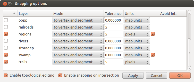
レイヤ単位での編集スナップオプション 
検索半径
検索半径とはあなたが地図をクリックした時に QGIS が最も近い頂点を 検索 するために使う距離です. 検索半径内に無い場合, QGIS は編集用頂点を見つけられず編集用頂点を選択できず警告がポップアップされます. スナップ許容値と検索半径は地図上の単位かピクセルで設定できます.そこで必要に応じて正しい値を設定することができます. もし大きな値を許容値に設定すると, QGIS は誤った頂点にスナップするでしょう, とりわけ多くの頂点を使うとそうなるでしょう. 検索半径を小さい値にすると何も見つからないはずでしょう.
レイヤにおける頂点編集のための検索半径の単位は Settings ‣ Options にある Digitizing タブで定義できます.同じ場所でプロジェクト全体のスナッピング許容値を定義することもできます.
ズームとパンニング
レイヤを編集する前に、対象のエリアにズームすべきです。これは、すべての頂点のマーカーが全体のレイヤに描画されている間待機するのを回避します。
ツールバーにある  pan や
pan や  zoom-in /
  zoom-out アイコンをマウスで利用するのとは別にマウスホィールやスペースバーと矢印キーでナビゲートができますi.
マウスホイールを使ったズームとパンニング
デジタイズを行っている間メインウィンドウでマウスホィールを使ってパンを行うことができます,そしてマウスホィールを転がすことで地図の拡大,縮小を行うことができます. 拡大を行う場合マウスカーソルを地図エリアで向こう側に(あなたと逆方向に)動かしてください,マウスカーソルを手前に(あなたのほうに)動かすと縮小します. マウスカーソルの位置はズームしたい位置の中心にあります. マウスホィールのズームの動作は Options メニューの Settings ‣ にある Map tools タブでカスタマイズできます.
矢印キーを使ったパン
デジタイズ作業時に矢印キーを使ってパンを行うことができます. マウスカーソルを地図エリアにおきクリックした後右矢印キーを押すと東にパンします,左矢印キーを押すと西にパンします,上矢印キーを押すと北にパンします.下矢印キーを押すと南にパンします.
スペースバーを地図のパン作業の中断に利用できます.キーボードの PgUp と PgDown キーを使うとデジタイジング作業を中断することなく地図の拡大、縮小を行うことができます.
トポロジ編集
レイヤベースのスナッピングオプション定義のそばでメニュー 設定 (または ファイル) の スナップオプション... ダイアログでいくつかのトポロジカル機能の指定ができます. ここではHere you can define  トポロジ編集を有効にする の指定ができ,またポリゴンレイヤに対して 交差禁止. の指定をすると新しいポリゴンの重なり部分が除去されます.
トポロジ編集を有効にする
The option Enable topological editing is for editing
and maintaining common boundaries in polygon mosaics. QGIS ‘detects’ a
shared boundary in a polygon mosaic, so you only have to move the vertex
once, and QGIS will take care of updating the other boundary.
新規ポリゴンの重なりの禁止
2つ目のトポロジカルオプションは 交差禁止. で, called 新規ポリゴンの重なり禁止 と呼ばれポリゴンモザイクでの重なりを禁止するものです. これにより隣接ポリゴンの迅速なデジタイズができます. もしあるポリゴンが存在しているところでこのオプションを使って隣接ポリゴンを重なる形でデジタイズすると QGIS は2つめのポリゴンを共通境界線で自動的にカットします.これによってユーザが共通境界線の頂点をデジタイズしなくていい利点ができます.
交差に対するスナッピングを有効にする
Another option is to use Enable snapping on intersection.
It allows you to snap on an intersection of background layers, even if there’s no vertex on
the intersection.
既存レイヤのデジタイズ
デフォルトで QGIS はレイヤをリードオンリイでロードします. これはたとえばマウスがすべってまちがってレイヤを編集するようなアクシデントにそなえるためです. しかしながらデータプロバイダが許可してデータソースが書き込み可能なら(たとえば ファイルがリードオンリイではない)レイヤはすべて編集のため選択できます .
In general, tools for editing vector layers are divided into a digitizing and an advanced digitizing toolbar, described in section 高度なデジタイジング. You can select and unselect both under Settings ‣ Toolbars ‣. Using the basic digitizing tools, you can perform the following functions:
アイコン |
目的 |
アイコン |
目的 |
|---|---|---|---|
 |
現在の編集 |
 |
編集切り替え |
 |
地物追加 点入力 |
 |
地物追加 線入力 |
 |
地物追加 ポリゴン入力 |
 |
フィーチャの移動 |
 |
ノードツール |
 |
選択したものの削除 |
 |
フィーチャの切り取り |
 |
フィーチャのコピー |
 |
フィーチャの貼り付け |
 |
レイヤ編集の保存 |
テーブル編集 ベクタレイヤ基本編集ツールバー
すべての編集セッションは 編集モード切替 オプションを選択することで開始できます. これはそのレイヤの凡例エントリでマウス右ボタンで表示されるコンテキストメニューにあります.
編集モードを開始,終了する別の方法としてデジタイジングツールバーの Toggle Editing Toggle editing ボタンを使うことができます. レイヤが編集モードになると頂点にマーカーが表示され,編集ツールバーのツールボタンが有効になります.
ちなみに
定期的に保存する
Remember to Save Layer Edits regularly. This will also
check that your data source can accept all the changes.
フィーチャの追加
You can use the Add Feature,
Add Feature or
Add Feature icons on the toolbar to put the QGIS cursor into
digitizing mode.
それぞれの地物に対し、まずジオメトリをデジタイズし、属性を入力します。ジオメトリをデジタイズするには、マップエリアで左クリックし新しい地物の最初の頂点を作成します。
ラインとポリゴンで点を追加する場合は入力したい位置にマウス左ボタンでクリックを続けてください.点の追加を終了したい場合は地図上のどこかをマウス右ボタンでクリックして地物のジオメトリ入力終了を確認して下さい.
The attribute window will appear, allowing you to enter the information for
the new feature. Figure_edit_2 shows setting attributes for a fictitious new
river in Alaska. In the Digitizing menu under the
Settings ‣ Options menu, you can also activate
Suppress attributes pop-up windows after each created feature and
Reuse last entered attribute values.
Figure Edit 2:
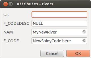
新しいベクタ地物のデジタイズの後で属性値を入力するダイアログ
With the Move Feature(s) icon on the toolbar, you can
move existing features.
ちなみに
属性値タイプ
For editing, the attribute types are validated during entry. Because of this, it is not possible to enter a number into a text column in the dialog Enter Attribute Values or vice versa. If you need to do so, you should edit the attributes in a second step within the Attribute table dialog.
現在の編集
This new feature allows the digitization of multiple layers. Choose
 Save for Selected Layers to save all changes you
made in multiple layers. You also have the opportunity to
Save for Selected Layers to save all changes you
made in multiple layers. You also have the opportunity to
 Rollback for Selected Layers, so that the
digitization may be withdrawn for all selected layers.
If you want to stop editing the selected layers,
Rollback for Selected Layers, so that the
digitization may be withdrawn for all selected layers.
If you want to stop editing the selected layers,  Cancel for Selected Layer(s)
is an easy way.
Cancel for Selected Layer(s)
is an easy way.
同じ機能がプロジェクトの全レイヤの編集で可能です.
ノードツール
For shapefile-based layers as well as SpatialLite, PostgreSQL/PostGIS, MSSQL Spatial, and Oracle Spatial tables, the
Node Tool provides manipulation capabilities of
feature vertices similar to CAD programs. It is possible to simply select
multiple vertices at once and to move, add or delete them altogether.
The node tool also works with ‘on the fly’ projection turned on, and it supports
the topological editing feature. This tool is, unlike other tools in
QGIS, persistent, so when some operation is done, selection stays
active for this feature and tool. If the node tool is unable to find any
features, a warning will be displayed.
It is important to set the property Settings ‣
Options ‣ Digitizing ‣ Search Radius:
 to a number greater than zero (i.e., 10). Otherwise, QGIS will
not be able to tell which vertex is being edited.
to a number greater than zero (i.e., 10). Otherwise, QGIS will
not be able to tell which vertex is being edited.
ちなみに
頂点マーカー
The current version of QGIS supports three kinds of vertex markers:
‘Semi-transparent circle’, ‘Cross’ and ‘None’. To change the marker style,
choose Options from the
Settings menu, click on the Digitizing
tab and select the appropriate entry.
基本操作
Start by activating the Node Tool and selecting a
feature by clicking on it. Red boxes will appear at each vertex of this feature.
- Selecting vertices: You can select vertices by clicking on them one at a time, by clicking on an edge to select the vertices at both ends, or by clicking and dragging a rectangle around some vertices. When a vertex is selected, its color changes to blue. To add more vertices to the current selection, hold down the Ctrl key while clicking. Hold down Ctrl or Shift when clicking to toggle the selection state of vertices (vertices that are currently unselected will be selected as usual, but also vertices that are already selected will become unselected).
- Adding vertices: To add a vertex, simply double click near an edge and a new vertex will appear on the edge near to the cursor. Note that the vertex will appear on the edge, not at the cursor position; therefore, it should be moved if necessary.
頂点の削除: 削除する頂点を選択した後 Delete キーをクリックして下さい. 注意
Node Tool は地物全部を削除することはできません; QGIS は作業している地物の大部で最低必要な数の頂点は確保します. 地物そのものを削除する場合は Delete Selected ツールを使って下さい.頂点の移動: 移動したい頂点を選択して下さい. 選択した頂点またはエッジをクリックして移動したい方向にドラッグして下さい. すべての選択した頂点は一緒に移動します. もしスナッピングが有効ならばすべての選択物はもっとも近い頂点かラインにジャンプすることもできます.
Each change made with the node tool is stored as a separate entry in the Undo dialog. Remember that all operations support topological editing when this is turned on. On-the-fly projection is also supported, and the node tool provides tooltips to identify a vertex by hovering the pointer over it.
地物の切り取り、コピーと貼り付け
Selected features can be cut, copied and pasted between layers in the same
QGIS project, as long as destination layers are set to
Toggle editing beforehand.
地物は、テキストなどの外部アプリケーションに貼り付けることができます。つまり、地物は、ジオメトリデータをOGC well-known Text(WKT)形式としてCSV形式で表現されます。
However, in this version of QGIS, text features from outside QGIS cannot be pasted to a layer within QGIS. When would the copy and paste function come in handy? Well, it turns out that you can edit more than one layer at a time and copy/paste features between layers. Why would we want to do this? Say we need to do some work on a new layer but only need one or two lakes, not the 5,000 on our big_lakes layer. We can create a new layer and use copy/paste to plop the needed lakes into it.
例として新しいレイヤにいくつかの湖沼をコピーします:
コピーしたいレイヤをロードします (ソースレイヤ)
コピー先にしたいレイヤをロードまたは作成します(ターゲットレイヤ)
ターゲットレイヤの編集を開始します
凡例をクリックしてソースレイヤをアクティブにします
- Use the
 Select Single Feature tool to select the
feature(s) on the source layer
Select Single Feature tool to select the
feature(s) on the source layer - Click on the Copy Features tool
判例をクリックしてコピー先レイヤをアクティブにして下さい
- Click on the Paste Features tool
編集モードを終了して変更内容を保存して下さい
ソースとターゲットレイヤのスキーマ(フィールド名と型が異なる場合)が異なる場合どうなるでしょうか? QGIS はマッチできる項目以外を無視します.もしあなたがターゲットレイヤにコピーする属性の内容にこだわらない場合はフィールドとデータタイプの設計は重要ではありません.すべてを - 地物とその属性 - 正しくコピーしたい場合はスキーマを一致させなければなりません.
ちなみに
貼り付け地物の一致
If your source and destination layers use the same projection, then the pasted features will have geometry identical to the source layer. However, if the destination layer is a different projection, then QGIS cannot guarantee the geometry is identical. This is simply because there are small rounding-off errors involved when converting between projections.
選択地物の削除
ポリゴン全体を削除したい場合最初に通常の Select Single Feature ツールでポリゴンを選択して下さい.削除のために複数の地物を選択することも可能です.選択を行うと Delete Selected ツールを使って地物を削除することができます.
The Cut Features tool on the digitizing toolbar can
also be used to delete features. This effectively deletes the feature but
also places it on a “spatial clipboard”. So, we cut the feature to delete.
We could then use the Paste Features tool to put it back,
giving us a one-level undo capability. Cut, copy, and paste work on the
currently selected features, meaning we can operate on more than one at a time.
編集レイヤの保存
When a layer is in editing mode, any changes remain in the memory of QGIS.
Therefore, they are not committed/saved immediately to the data source or disk.
If you want to save edits to the current layer but want to continue editing
without leaving the editing mode, you can click the
Save Layer Edits button. When you turn editing mode off with
Toggle editing (or quit QGIS for that matter),
you are also asked if you want to save your changes or discard them.
もし変更が保存されなかった場合 (たとえば., ディスクが満杯だとか属性の値が指定の範囲の外であるとか), QGIS はメモリーの状態を保存します. これによって編集内容を調整して再度保存を試すことができます.
ちなみに
データの整合性
編集作業を開始する前にデータソースをバックアップしておくことは良いアイデアです. QGIS の作者たちはデータの整合性を保つために努力しています,しかしそれらについて保証はしていません
高度なデジタイジング
アイコン |
目的 |
アイコン |
目的 |
|---|---|---|---|
 |
アンドゥ |
 |
リドゥ |
 |
フィーチャ(群)の回転 |
 |
地物の簡素化 |
 |
リングの追加 |
 |
パートの追加 |
 |
リングの塗りつぶし |
 |
リングの削除 |
 |
パートの削除 |
 |
地物の変形 |
 |
オフセットカーブ |
 |
地物の分割 |
 |
部分の分割 |
 |
選択地物の結合 |
 |
選択地物の属性の結合 |
 |
ポイントシンボルの回転 |
高度なテーブル編集: ベクタレイヤの高度な編集ツールバー
アンドゥとリドゥ
取り消し と 再実行 ツールを使うとベクタ編集操作の取り消しや再実行を行うことができます.取り消し/再実行操作の全履歴を表示できる結合表示可能なウィジェットもあります ( Figure_edit_3 参照). このウィジェットはデフォルトでは表示されていません; このウィジェットはツールバー上でマウス右ボタンをクリックして取り消し/再実行チェックボックスをアクティブにすることで表示できます. ウィジェットが表示されていなくても取り消し/再実行機能は有効です.
Figure Edit 3:
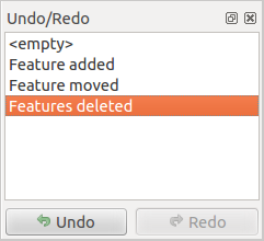
デジタイジングステップのリドゥとアンドゥ
When Undo is hit, the state of all features and attributes are reverted to the state before the reverted operation happened. Changes other than normal vector editing operations (for example, changes done by a plugin), may or may not be reverted, depending on how the changes were performed.
undo/redo ヒストリウィジェットを利用する場合単純に操作のヒストリリストをクリックして下さい. すべての操作は選択操作のあとであった状態に戻されます.
フィーチャ(群)の回転
Use Rotate Feature(s) to rotate one or multiple
selected features in the map canvas. You first need to select the features
and then press the Rotate Feature(s) icon. The
centroid of the feature(s) appears and will be the rotation anchor point. If you selected
multiple features, the rotation anchor point will be the common center of the features.
Press and drag the left mouse button in the desired direction to rotate the
selected features.
It’s also possible to create a user-defined rotation anchor point around which the selected feature will rotate.
Select the features to rotate and activate the Rotate Feature(s) tool.
Press and hold the Ctrl button and move the mouse pointer (without pressing the mouse button)
to the place where you want the rotation anchor to be moved. Release the Ctrl button
when the desired rotation anchor point is reached. Now, press and drag the left mouse button
in the desired direction to rotate the selected feature(s).
地物の簡素化
The Simplify Feature tool allows you to reduce the
number of vertices of a feature, as long as the geometry doesn’t change.
First, select a feature. It will be highlighted by a red rubber band
and a slider will appear. Moving the slider, the red rubber band will change
its shape to show how the feature is being simplified. Click [OK] to store
the new, simplified geometry. If a feature cannot be simplified
(e.g. multi-polygons), a message will appear.
リングの追加
You can create ring polygons using the
Add Ring icon in the toolbar. This means that inside an existing area, it
is possible to digitize further polygons that will occur as a ‘hole’, so
only the area between the boundaries of the outer and inner polygons remains
as a ring polygon.
パートの追加
You can add part polygons to a selected
multipolygon. The new part polygon must be digitized outside
the selected multi-polygon.
リングの塗りつぶし
You can use the Fill Ring function to add a ring to
a polygon and add a new feature to the layer at the same time. Thus you need not
first use the Add Ring icon and then the
Add feature function anymore.
リングの削除
The Delete Ring tool allows you to delete ring polygons
inside an existing area. This tool only works with polygon layers. It doesn’t
change anything when it is used on the outer ring of the polygon. This tool
can be used on polygon and multi-polygon features. Before you select the
vertices of a ring, adjust the vertex edit tolerance.
パートの削除
The Delete Part tool allows you to delete parts from
multifeatures (e.g., to delete polygons from a multi-polygon feature). It won’t
delete the last part of the feature; this last part will stay untouched. This
tool works with all multi-part geometries: point, line and polygon. Before you
select the vertices of a part, adjust the vertex edit tolerance.
地物の変形
You can reshape line and polygon features using the
Reshape Features icon on the toolbar. It replaces the line or polygon
part from the first to the last intersection with the original line. With
polygons, this can sometimes lead to unintended results. It is mainly useful
to replace smaller parts of a polygon, not for major overhauls, and the reshape
line is not allowed to cross several polygon rings, as this would generate an
invalid polygon.
たとえばポリゴンの境界線をこのツールで編集できます. 最初にポリゴンの内側をクリックした後に新しく頂点を追加したい位置に点を入力してください. それから境界線をまたいでポリゴンの外側に頂点を追加してください. このツールは境界線と新しい線の交点に自動的にノードを追加します. これはポリゴンの一部を削除する場合にも利用できます, ポリゴンの外側から新しいラインを開始して内側に新しい頂点を追加します,そしてポリゴンの外側に最終点を右ボタンクリックで作成してください.
ノート
The reshape tool may alter the starting position of a polygon ring or a closed line. So, the point that is represented ‘twice’ will not be the same any more. This may not be a problem for most applications, but it is something to consider.
オフセットカーブ
The Offset Curve tool creates parallel shifts of line layers.
The tool can be applied to the edited layer (the geometries are modified)
or also to background layers (in which case it creates copies of the lines / rings and adds them to the the edited layer).
It is thus ideally suited for the creation of distance line layers. The displacement is
shown at the bottom left of the taskbar.
To create a shift of a line layer, you must first go into editing mode and then
select the feature. You can make the Offset Curve tool active and drag
the cross to the desired distance. Your changes may then be saved with the
Save Layer Edits tool.
地物の分割
ツールバー上の Split Features アイコンを使って地物を分割できます. 分割したい地物を交差する線を描画すれば分割できます.
部分の分割
In QGIS 2.0 it is now possible to split the parts of a multi part feature so that the
number of parts is increased. Just draw a line across the part you want to split using
the Split Parts icon.
選択フィーチャのマージ
The Merge Selected Features tool allows you to merge
features that have common boundaries and the same attributes.
選択地物の属性マージ
The Merge Attributes of Selected Features tool
allows you to merge attributes of features with common boundaries and
attributes without merging their boundaries.
First, select several features at once. Then
press the Merge Attributes of Selected Features button.
Now QGIS asks you which attributes are to be applied to all selected objects.
As a result, all selected objects have the same attribute entries.
ポイントシンボルの回転
Rotate Point Symbols allows you to change the rotation
of point symbols in the map canvas. You must first define a rotation column
from the attribute table of the point layer in the Advanced menu of the
Style menu of the Layer Properties. Also, you will need to
go into the ‘SVG marker’ and choose Data defined properties ....
Activate Angle and choose ‘rotation’ as field.
Without these settings, the tool is inactive.
Figure Edit 4:
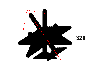
ポイントシンボルの回転
To change the rotation, select a point feature in the map canvas and rotate it, holding the left mouse button pressed. A red arrow with the rotation value will be visualized (see Figure_edit_4). When you release the left mouse button again, the value will be updated in the attribute table.
ノート
If you hold the Ctrl key pressed, the rotation will be done in 15 degree steps.
新しいベクタレイヤの作成
QGIS では新規の Shapefile レイヤを作ることができます, 新規 SpatiaLite レイヤと新規GPX レイヤを作ることができます. 新規 GRASSレイヤの作成はGRASS-pluginででサポートされています. GRASS ベクタレイヤ作成の詳しい情報はセクション 新しいGRASSベクターレイヤーの作成 を参照して下さい.
新規Shapefileレイヤの作成
To create a new shape layer for editing, choose New ‣
 New Shapefile Layer... from the
Layer menu. The New Vector Layer dialog will be
displayed as shown in Figure_edit_5. Choose the type of layer (point, line or
polygon) and the CRS (coordinate reference system).
New Shapefile Layer... from the
Layer menu. The New Vector Layer dialog will be
displayed as shown in Figure_edit_5. Choose the type of layer (point, line or
polygon) and the CRS (coordinate reference system).
注 QGIS はまだ 2.5D 地物の作成をサポートしていません (例. X,Y,Z座標を持つ地物).
Figure Edit 5:
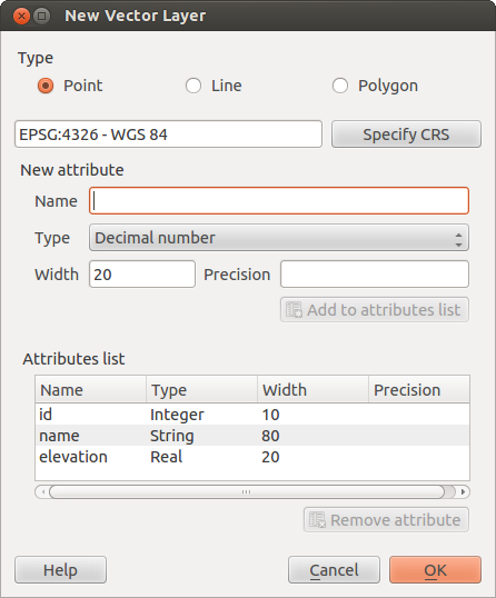
新規Shapefile作成ダイアログ
To complete the creation of the new shapefile layer, add the desired attributes
by clicking on the [Add to attributes list] button and specifying a name and type for the
attribute. A first ‘id’ column is added as default but can be removed, if not
wanted. Only Type: real  , Type: integer
, Type: string and Type:date
attributes are supported. Additionally and according to the attribute type, you can also define
the width and precision of the new attribute column. Once you are happy with
the attributes, click [OK] and provide a name for the shapefile. QGIS will
automatically add a .shp extension to the name you specify. Once the
layer has been created, it will be added to the map, and you can edit it in the
same way as described in section 既存レイヤのデジタイズ above.
, Type: integer
, Type: string and Type:date
attributes are supported. Additionally and according to the attribute type, you can also define
the width and precision of the new attribute column. Once you are happy with
the attributes, click [OK] and provide a name for the shapefile. QGIS will
automatically add a .shp extension to the name you specify. Once the
layer has been created, it will be added to the map, and you can edit it in the
same way as described in section 既存レイヤのデジタイズ above.
新規Spatialiteレイヤの作成
編集用に新しい SpatiaLite レイヤを作成するために Layer メニューで New ‣  New SpatiaLite Layer... を選択して下さい. New SpatiaLite Layer ダイアログが Figure_edit_6 のように表示されます.
Figure Edit 6:
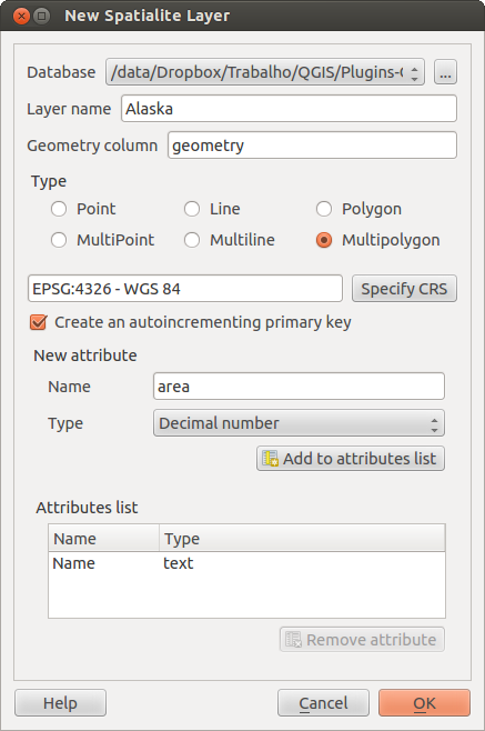
新規Spatialiteレイヤ作成ダイアログ
The first step is to select an existing SpatiaLite database or to create a new
SpatiaLite database. This can be done with the browse button  to
the right of the database field. Then, add a name for the new layer, define
the layer type, and specify the coordinate reference system with [Specify CRS].
If desired, you can select Create an autoincrementing primary key.
to
the right of the database field. Then, add a name for the new layer, define
the layer type, and specify the coordinate reference system with [Specify CRS].
If desired, you can select Create an autoincrementing primary key.
To define an attribute table for the new SpatiaLite layer, add the names of the attribute columns you want to create with the corresponding column type, and click on the [Add to attribute list] button. Once you are happy with the attributes, click [OK]. QGIS will automatically add the new layer to the legend, and you can edit it in the same way as described in section 既存レイヤのデジタイズ above.
SpatiaLiteレイヤ の高度な管理はDB マネージャを使うと実行できます DB マネージャプラグイン 参照.
新しいGPXレイヤの作成
新しい GPXファイルを作成するためには GPS プラグインを最初にロードする必要があります. Plugins ‣  Plugin Manager... で Plugin Manager ダイアログを開いてください. GPS Tools チェックボックスをアクティブにして下さい.
このプラグインがロードされると Layer メニューで New ‣  Create new GPX Layer... を選択できます. Save new GPX file as ダイアログで新しい GPX レイヤを保存する場所を選べます.
属性テーブルの作業
属性テーブル では選択されたレイヤの地物を表示します. テーブルの各行は地図の1個の地物を表します, そしてそれぞれのカラムは地物の情報を保持しています. テーブルの地物は検索,選択,移動,編集さえもできます.
To open the attribute table for a vector layer, make the layer active by
clicking on it in the map legend area. Then, from the main
Layer menu, choose  Open Attribute
Table. It is also possible to right click on the layer and choose
Open Attribute Table from the drop-down menu,
and to click on the Open Attribute Table button
in the Attributes toolbar.
Open Attribute
Table. It is also possible to right click on the layer and choose
Open Attribute Table from the drop-down menu,
and to click on the Open Attribute Table button
in the Attributes toolbar.
これによってレイヤの地物の属性を表示する新しいウィンドウが開きます (figure_attributes_1). 属性テーブルのタイトルに地物の数と選択されている地物の数が表示されます.
Figure Attributes 1:
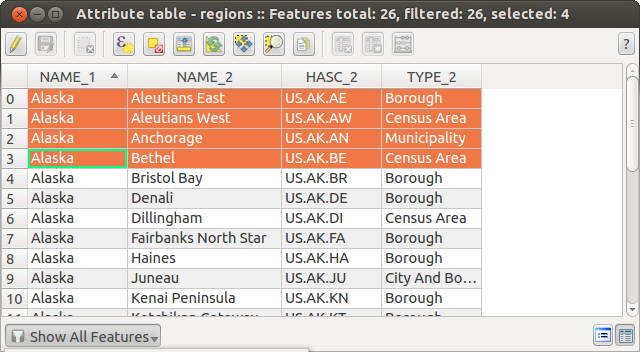
領域レイヤの属性テーブル
属性テーブルにおける地物の選択
Each selected row in the attribute table displays the attributes of a selected feature in the layer. If the set of features selected in the main window is changed, the selection is also updated in the attribute table. Likewise, if the set of rows selected in the attribute table is changed, the set of features selected in the main window will be updated.
Rows can be selected by clicking on the row number on the left side of the row. Multiple rows can be marked by holding the Ctrl key. A continuous selection can be made by holding the Shift key and clicking on several row headers on the left side of the rows. All rows between the current cursor position and the clicked row are selected. Moving the cursor position in the attribute table, by clicking a cell in the table, does not change the row selection. Changing the selection in the main canvas does not move the cursor position in the attribute table.
The table can be sorted by any column, by clicking on the column header. A small arrow indicates the sort order (downward pointing means descending values from the top row down, upward pointing means ascending values from the top row down).
For a simple search by attributes on only one column, choose the Column filter ‣ from the menu in the bottom left corner. Select the field (column) on which the search should be performed from the drop-down menu, and hit the [Apply] button. Then, only the matching features are shown in the attribute table.
To make a selection, you have to use the  Select features using an Expression
icon on top of the attribute table.
Select features using an Expression allows you
to define a subset of a table using a Function List like in the
Select features using an Expression
icon on top of the attribute table.
Select features using an Expression allows you
to define a subset of a table using a Function List like in the
 Field Calculator (see フィールド計算機).
The query result can then be saved as a new vector layer.
For example, if you want to find regions that are boroughs from regions.shp
of the QGIS sample data, you have to open the Fields and Values menu
and choose the field that you want to query. Double-click the field ‘TYPE_2’ and also
[Load all unique values] . From the list, choose and double-click ‘Borough’.
In the Expression field, the following query appears:
Field Calculator (see フィールド計算機).
The query result can then be saved as a new vector layer.
For example, if you want to find regions that are boroughs from regions.shp
of the QGIS sample data, you have to open the Fields and Values menu
and choose the field that you want to query. Double-click the field ‘TYPE_2’ and also
[Load all unique values] . From the list, choose and double-click ‘Borough’.
In the Expression field, the following query appears:
"TYPE_2" = 'Borough'
Here you can also use the Function list ‣ Recent (Selection) to make a selection that you used before. The expression builder remembers the last 20 used expressions.
The matching rows will be selected, and the total number of matching rows will appear in the title bar of the attribute table, as well as in the status bar of the main window. For searches that display only selected features on the map, use the Query Builder described in section クエリビルダー.
選択されたレコードのみを表示したい場合右下のメニューの Show Selected Features を利用して下さい.
属性テーブルの上部にあるその他のボタンは以下のような機能を提供しています:
- 編集モードの切替 単一の値を編集して以下の機能を利用可能にします( Ctrl+E でも実行可能 )
- 編集の保存 ( Ctrl+S でも実行可能 )
 全選択解除 ( Ctrl+U でも実行可能 )
 選択を先頭に移動 ( Ctrl+T でも実行可能 )
 選択部分の反転 ( Ctrl+R でも実行可能 )
 選択している行をクリップボードにコピー ( Ctrl+C でも実行可能 )
 選択行の地物に地図をズームする ( Ctrl+J でも実行可能 )
 選択行の地物に地図をパンする ( Ctrl+P でも実行可能 )
- 選択地物の削除 ( Ctrl+D でも実行可能 )
 新規カラム PostGIS レイヤまたはGDAL version >= 1.6の場合の OGRレイヤ用 ( Ctrl+W でも実行可能 )
 カラムの削除 PostGIS レイヤまたはGDAL version >= 1.9の場合のOGR レイヤ用 ( Ctrl+L でも実行可能 )
- フィールド計算機を開く ( Ctrl+I でも実行可能 )
ちなみに
WKT ジオメトリのスキップ
もし属性データを外部プログラム(たとえばExcel)で利用したい場合 Copy selected rows to clipboard ボタンを利用して下さい. Settings ‣ Options ‣ Data sources menu Copy geometry in WKT representation from attribute table を無効にしている場合に,このボタンを利用するとベクタジオメトリ抜きで情報をコピーできます.
選択地物を新規レイヤに保存する
The selected features can be saved as any OGR-supported vector format and also transformed into another coordinate reference system (CRS). Just open the right mouse menu of the layer and click on Save selection as ‣ to define the name of the output file, its format and CRS (see section 地図凡例). It is also possible to specify OGR creation options within the dialog.
新しいレイヤへのペースト
Features that are on the clipboard may be pasted into a new layer. To do this, first make a layer editable. Select some features, copy them to the clipboard, and then paste them into a new layer using Edit ‣ Paste Features as and choosing New vector layer or New memory layer.
これは QGIS で選択しコピーされた地物に対し、またはwell-known text (WKT)を使って定義された他のソース由来の地物に対して適用されます。
空間的でない属性テーブルの作業
QGIS では空間情報が無いテーブルをロードすることができます. この機能は OGRでサポートされているテーブルや, デリミテッドテキストと同じように PostgreSQL, MSSQL とOracle プロバイダで利用できます. テーブルに対してフィールドのルックアップや一般的な閲覧,編集をテーブルビューで行うことができます. テーブルをロードすると凡例フィールドに表示されます. これはたとえば Open Attribute Table ツールで開くことができ他の属性テーブルと同じように編集できます.
As an example, you can use columns of the non-spatial table to define attribute values, or a range of values that are allowed, to be added to a specific vector layer during digitizing. Have a closer look at the edit widget in section フィールドメニュー to find out more.
1対多リレーションの作成
リレーションは、多くの場合、データベースで使用される技術である。概念は、異なるレイヤ(テーブル)の地物(行)は、相互に属することができるということです。
例としてアラスカ全域(ポリゴン)データで名前と領域タイプとユニークid(プライマリキーとして動作します)を属性として持つものがあります.
外部キー
Then you get another point layer or table with information about airports that are located in the regions and you also want to keep track of these. If you want to add them to the region layer, you need to create a one to many relation using foreign keys, because there are several airports in most regions.
Figure Relations 1:
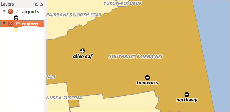
Alaska 領域の空港
In addition to the already existing attributes in the airports attribute table another field fk_region which acts as a foreign key (if you have a database, you will probably want to define a constraint on it).
This field fk_region will always contain an id of a region. It can be seen like a pointer to the region it belongs to. And you can design a custom edit form for the editing and QGIS takes care about the setup. It works with different providers (so you can also use it with shape and csv files) and all you have to do is to tell QGIS the relations between your tables.
レイヤ
QGIS makes no difference between a table and a vector layer. Basically, a vector layer is a table with a geometry. So can add your table as a vector layer. To demostrate you can load the ‘region’ shapefile (with geometries) and the ‘airport’ csv table (without geometries) and a foreign key (fk_region) to the layer region. This means, that each airport belongs to exactly one region while each region can have any number of airports (a typical one to many relation).
定義(リレーションマネージャー)
最初に行うべきことは QGIS にレイヤ間のリレーションを教えることです. それは 設定 ‣ プロジェクトプロパティ でできます. リレーション メニューを開いて 追加 をクリックして下さい.
名称 はタイトルとして使われます. これは人間が読んでわかり文字列にするべきです, そしてこのリレーションがどういう意味なのかわかるような文字にするべきです. 今回のサンプルでは “Airports” とします.
参照レイヤ とは外部キーフィールドを持つレイヤです. 私たちの例では airports レイヤです
参照フィールド とは他のレイヤとリンクするフィールドです 私たちの例では fk_region です
参照先レイヤ とはプライマリキーでリンクするレイヤです,私たちの例ではregions レイヤになります
参照先フィールド は参照先レイヤのプライマリキーです,今回の例では ID です
id は内部の用途で使われます,この値はユニークでなければいけません. これがサポートされる場合カスタムフォームをサポートする必要があります. もしここを空白にしていた場合自動的に生成されますが,扱いやすいものがある場合自分で設定することもできます.
Figure Relations 2:

リレーションマネージャ
フォーム
Now that QGIS knows about the relation, it will be used to improve the forms it generates. As we did not change the default form method (autogenerated) it will just add a new widget in our form. So let’s select the layer region in the legend and use the identify tool. Depending on your settings, the form might open directly or you will have to choose to open it in the identification dialog under actions.
Figure Relations 3:
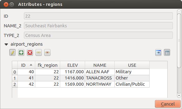
airports のリレーションを表示した地物特定ダイアログ
As you can see, the airports assigned to this particular region are all shown in a table. And there are also some buttons available. Let’s review them shortly
- The button is for toggling the edit mode. Be aware that it toggles the edit mode of the airport layer, although we are in the feature form of a feature from the region layer. But the table is representing features of the airport layer.
- The
 button will add a new feature to the airport layer. And it will assign the new airport to the current region by default.
 - The
 button will delete the selected airport permanently.
 - The
 symbol will open a new dialog where you can select any existing airport which will then be assigned to the current region. This may be handy if you created the airport on the wrong region by accident.
 - The
 symbol will unlink the selected airport from the current region, leaving them unassigned (the foreign key is set to NULL) effectively.
 - The two buttons to the right switch between table view and form view where the later let’s you view all the airports in their respective form.
If you work on the airport table, a new widget type is available which lets you embed the feature form of the referenced region on the feature form of the airports. It can be used when you open the layer properties of the airports table, switch to the Fields menu and change the widget type of the foreign key field ‘fk_region’ to Relation Reference.
If you look at the feature dialog now, you will see, that the form of the region is embedded inside the airports form and will even have a combobox, which allows you to assign the current airport to another region.
Figure Relations 4:
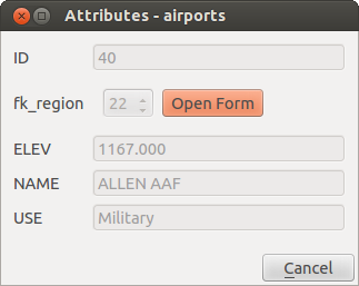
Identification dialog airport with relation to regions