ベクタ属性データ
 |
目的: |
ここでは属性データをどのようにベクタデータと結びつけ, シンボルを変更するかについて扱います. |
キーワード: |
属性, データベース, フィールド, データ, ベクタ, シンボロジー |
概要
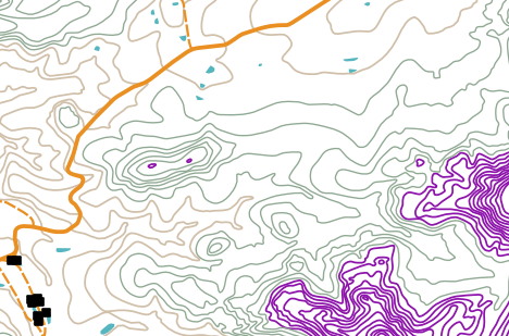
もし地図上の全てのラインの色, 幅, 厚み, そしてラベルも同じだとしたら, 非常にわかりづらいでしょう.そのような地図からは少しの情報しか読み取ることができません.例として, figure_map_attributes を見てみましょう.
Figure Attributes on map:
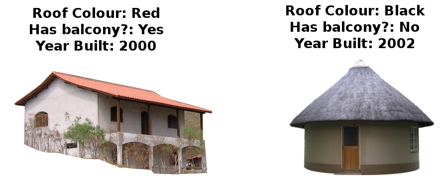
ここではどのように属性データによって面白くて役に立つ地図を作ることができるのかを見ていきましょう.前のベクタデータの項目では**ベクタデータの記述** に使われる 属性データ について簡単に説明をしました.figure_house の家の写真を見てみましょう.
Figure House 1:
これらの家のジオメトリはポリゴン (家の見取り図) で, 記録済みの属性情報は屋根の色, バルコニーの有無と建築年です.属性情報は目に見えるものとは限らず – 建築年のような情報も含むことができます.GISアプリケーションでは家の地物タイプと属性テーブルに含まれる属性情報を表現することができます ( figure_house_gis 参照) .
Figure House 2:
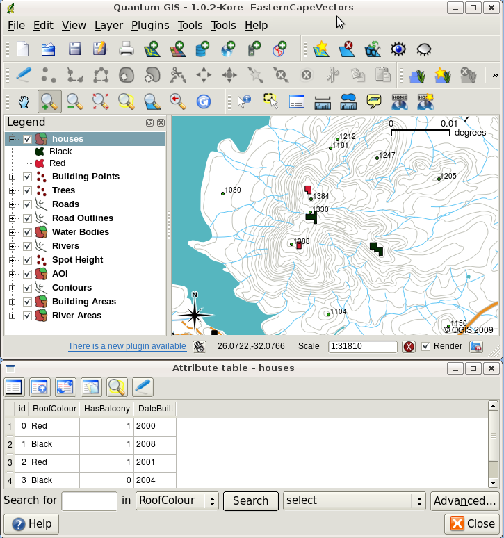
家のレイヤ。 家の地物には、屋根の色等の属性やその他属性情報が記述されています。 属性テーブル (下図)には、地図上に示された領域の家の属性のリストが示されています。 テーブルの中でハイライトされている属性、地図上で黄色で選択されているポリゴンの情報になります。
The fact that features have attributes as well geometry in a GIS Application opens up many possibilities. For example we can use the attribute values to tell the GIS what colours and style to use when drawing features (see figure_style_by_attribute). The process of setting colours and drawing styles is often referred to as setting feature symbology.
Figure Feature Style 1:
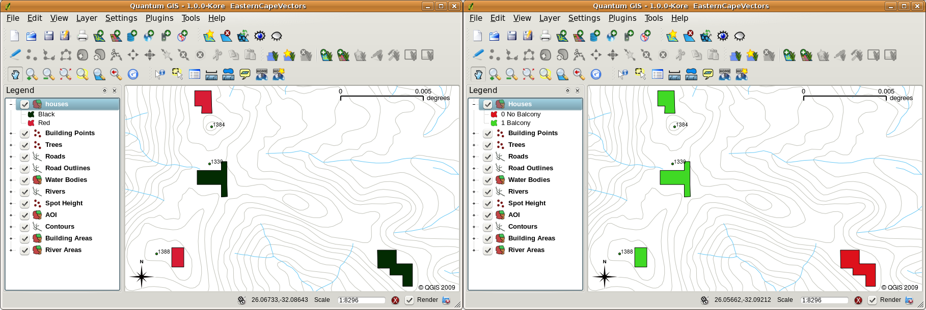
GISアプリケーションでは、属性に応じて異なる地物を描画することができます。例えば左図では、家の屋根の色の属性と同じ色で、家のポリゴンを描画しています。右図では、バルコニーの有無に応じて、家のポリゴンを塗り分けています。
属性データはまた ** マップラベル**を作成する場合にも役立ちます。ほとんどのGISアプリケーションは各地物にラベルを付けるために使用されるべき属性を選択する機能を持つでしょう。
If you have ever searched a map for a place name or a specific feature, you will know how time consuming it can be. Having attribute data can make searching for a specific feature quick and easy. In figure_search_by_attribute you can see an example of an attribute search in a GIS.
Figure Feature Search 1:
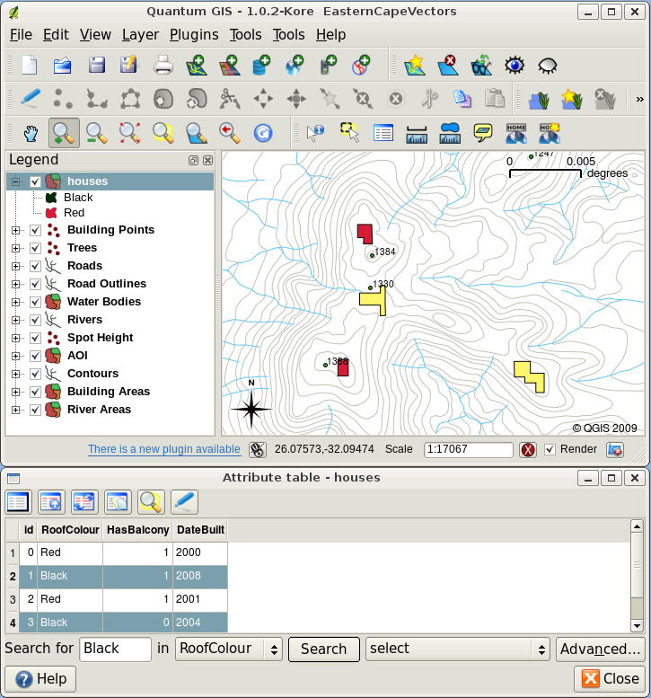
In a GIS Application, we can also search for features based on their attributes. Here we see a search for houses with black roofs. Results are shown in yellow in the map, turquoise on the table.
Finally, attribute data can be very useful in carrying out spatial analysis. Spatial analysis combines the spatial information stored in the geometry of features with their attribute information. This allows us to study features and how they relate to each other. There are many types of spatial analysis that can be carried out, for example, you could use GIS to find out how many red roofed houses occur in a particular area. If you have tree features, you could use GIS to try to find out which species might be affected if a piece of land is developed. We can use the attributes stored for water samples along a river course to understand where pollution is entering into the stream. The possibilities are endless! In a later topic we will be exploring spatial analysis in more detail.
属性データの詳細に移る前に、簡単にまとめてみましょう。
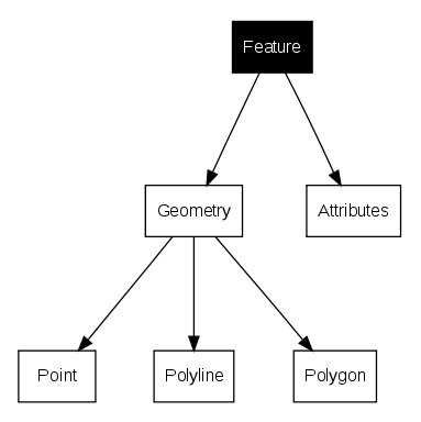
Features are real world things such as roads, property boundaries, electrical substation sites and so on. A feature has a geometry (which determines if it is a point, polyline or polygon) and attributes (which describe the feature). This is shown in figure_features_at_glance.
Figure Feature Summary 1:
属性の詳細
Attributes for a vector feature are stored in a table. A table is like a spreadsheet. Each column in the table is called a field. Each row in the table is a record. Table table_house_attributes shows a simple example of how an attribute table looks in a GIS. The records in the attribute table in a GIS each correspond to one feature. Usually the information in the attribute table is stored in some kind of database. The GIS application links the attribute records with the feature geometry so that you can find records in the table by selecting features on the map, and find features on the map by selecting features in the table.
属性テーブル |
フィールド1 : YearBuilt |
フィールド2: RoofColour |
フィールド3: Balcony |
|---|---|---|---|
レコード1 |
1998 | 赤 |
はい |
レコード2 |
2000 | 黒 |
いいえ |
レコード3 |
2001 | 銀色 |
はい |
家の属性表1: 属性テーブルはフィールド (列) とレコード (行) を持っています.
Each field in the attribute table contains contains a specific type of data –– text, numeric or date. Deciding what attributes to use for a feature requires some thought and planning. In our house example earlier on in this topic, we chose roof colour, presence of a balcony and month of construction as attributes of interest. We could just as easily have chosen other aspects of a house such as:
階数
部屋数
居住者数
住居の種類(RDPハウス、アパートのブロック、小屋、れんが造りの家など)
家が建てられた年
家の床面積
他には....
With so many options, how do we make a good choice as to what attributes are needed for a feature? It usually boils down to what you plan to do with the data. If you want to produce a colour coded map showing houses by age, it will make sense to have a ‘Year Built’ attribute for your feature. If you know for sure you will never use this type of map, it is better to not store the information. Collecting and storing unneeded information is a bad idea because of the cost and time required to research and capture the information. Very often we obtain vector data from companies, friends or the government. In these cases it is usually not possible to request specific attributes and we have to make do with what we get.
単一シンボル
If a feature is symbolised without using any attribute table data, it can only be drawn in a simple way. For example with point features you can set the colour and marker (circle, square, star etc.) but that is all. You cannot tell the GIS to draw the features based on one of its properties in the attribute table. In order to do that, you need to use either a graduated, continuous or unique value symbol. These are described in detail in the sections that follow.
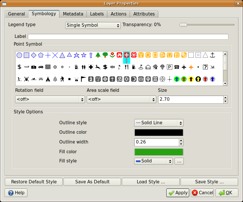
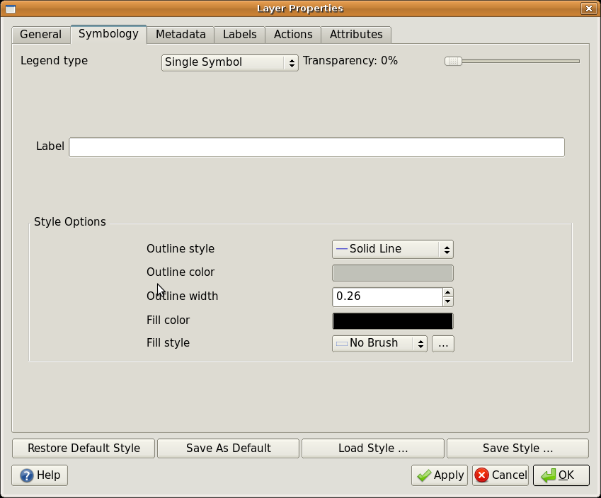
A GIS application will normally allow you to set the symbology of a layer using a dialog box such as the one shown in in figure_single_symbol_1. In this dialog box you can choose colours and symbol styles. Depending on the geometry type of a layer, different options may be shown. For example with point layers you can choose a marker style. With line and polygon layers there is no marker style option, but instead you can select a line style and colour such as dashed orange for gravel roads, solid orange for minor roads, and so on (as shown in figure_single_symbol_2). With polygon layers you also have the option of setting a fill style and color.
Figure Single Symbol 1:
Figure Single Symbol 2:
階調シンボル
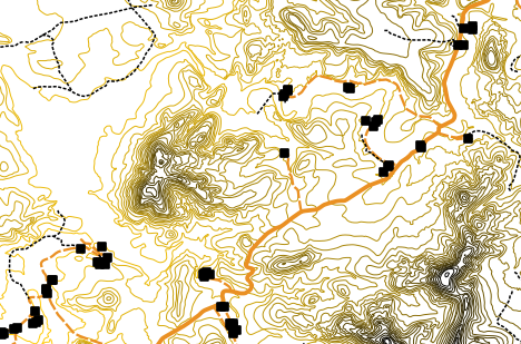
Sometimes vector features represent things with a changing numerical value. Contour lines are a good example of this. Each contour usually has an attribute value called ‘height’ that contains information about what height that contour represents. In earlier in this topic we showed contours all drawn with the same colour. Adding colour to the contours can help us to interpret the meanings of contours. For example we can draw low lying areas with one colour, mid-altitude areas with another and high-altitude areas with a third.
Figure Graduated Symbol 1:
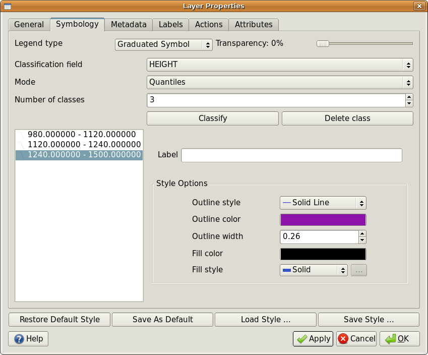
The height attribute of contours can be used to separate the contours into 3 classes. Contours between 980 m and 1120 m will be drawn in brown, those between 1120 m and 1240 m in green and those between 1240 m and 1500 m in purple.
Figure Graduated Symbol 2:
Setting colours based on discrete groups of attribute values is called Graduated Symbology in QGIS. The process is shown in Illustrations figure_graduated_symbol_1 and figure_graduated_symbol_2. Graduated symbols are most useful when you want to show clear differences between features with attribute values in different value ranges. The GIS Application will analyse the attribute data (e.g. height) and, based on the number of classes you request, create groupings for you. This process is illustrated in table_graduated_1.
属性値 |
クラスと色 |
|---|---|
| 1 | クラス1 |
| 2 | クラス1 |
| 3 | クラス1 |
| 4 | クラス2 |
| 5 | クラス2 |
| 6 | クラス2 |
| 7 | クラス3 |
| 8 | クラス3 |
| 9 | クラス3 |
Table Graduaded 1: Graduated colour breaks up the attribute value ranges into the number of classes you select. Each class is represented by a different colour.
連続カラーシンボル
In the previous section on Graduated Colour symbols we saw that we can draw features in discrete groups or classes. Sometimes it is useful to draw features in a colour range from one colour to another. The GIS Application will use a numerical attribute value from a feature (e.g. contour heights or pollution levels in a stream) to decide which colour to use. Table table_continuous_1 shows how the attribute value is used to define a continuous range of colours.
属性値 |
カラー(無階級またはグルーピング) |
|---|---|
| 1 | |
| 2 | |
| 3 | |
| 4 | |
| 5 | |
| 6 | |
| 7 | |
| 8 | |
| 9 |
Table Continuous 1: Continuous colour symbology uses a start colour (e.g. light orange shown here) and an end colour (e.g. dark brown shown here) and creates a series of shades between those colours.
Using the same contours example we used in the previous section, let’s see how a map with continuous colour symbology is defined and looks. The process starts by setting the layers properties to continuous colour using a dialog like the one shown in figure_continuos_symbol_1.
Figure Continuous Symbol 1:
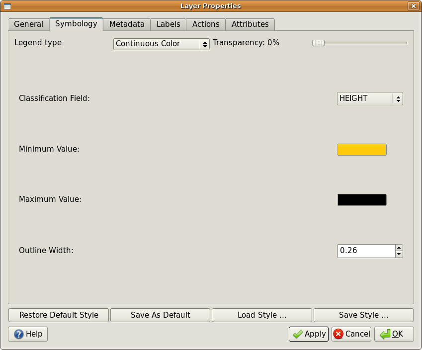
Setting up continuous colour symbology. The contour height attribute is used to determine colour values. Colours are defined for the minimum and maximum values. The GIS Application will then create a gradient of colours for drawing the features based on their heights.
After defining the minimum and maximum colours in the colour range, the colour features are drawn in will depend on where the attribute lies in the range between minimum and maximum. For example if you have contour features with values starting at 1000 m and ending at 1400 m, the value range is 1000 to 1400. If the colour set for the minimum value is set to orange and the colour for the maximum value is black, contours with a value of close to 1400 m will be drawn close to black. On the other hand contours with a value near to 1000 m will be drawn close to orange (see figure_continuous_symbol_2).
Figure Graduated Symbol 2:
単一シンボル
Sometimes the attributes of features are not numeric, but instead strings are used. ‘String’ is a computer term meaning a group of letters, numbers and other writing symbols. Strings attributes are often used to classify things by name. We can tell the GIS Application to give each unique string or number its own colour and symbol. Road features may have different classes (e.g. ‘street’, ‘secondary road’, ‘main road’ etc.), each drawn in the map view of the GIS with different colours or symbols. This is illustrated in table_unique_1.
属性値 |
色クラスとシンボル |
|---|---|
幹線道路 |
|
本道 |
|
周辺道路 |
|
通り |
Table Unique 1: 地物タイプ(e.g. 道路)のユニークな属性値で各々のシンボルを持つ。
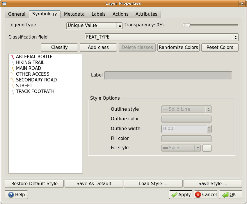
Within the GIS Application we can open/choose to use Unique Value symbology for a layer. The GIS will scan through all the different string values in the attribute field and build a list of unique strings or numbers. Each unique value can then be assigned a colour and style. This is shown in figure_unique_symbol_1.
Figure Unique Symbol 1:
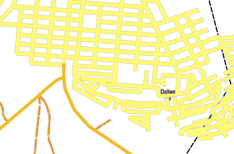
When the GIS draws the layer, it will look at the attributes of each feature before drawing it to the screen. Based on the value in the chosen field in the attribute table, the road line will be drawn with suitable colour and line style (and fill style if its a polygon feature). This is shown in figure_unique_symbol_2.
Figure Unique Symbol 2:
注意すべき点
Deciding which attributes and symbology to use requires some planning. Before you start collecting any GeoSpatial data, you should ensure you know what attributes are needed and how it will be symbolised. It is very difficult to go back and re-collect data if you plan poorly the first time around. Remember also that the goal of collecting attribute data is to allow you to analyse and interpret spatial information. How you do this depends on the questions you are trying to answer. Symbology is a visual language that allows people to see and understand your attribute data based on the colours and symbols you use. Because of this you should put a lot of thought into how you symbolise your maps in order to make them easy to understand.
わかりましたか?
ここでは以下のことを学びました:
ベクタデータは attributes を持っています
地物の 情報 を 記述 する属性
属性は テーブル に格納されます
テーブルの行は レコード と呼ばれます
ベクタレイヤでは それぞれの地物ごとにレコード があります
テーブルの列は フィールド と呼ばれます
フィールドは地物の持つ 情報 (例. 高さ, 屋根の色)を表します
フィールドは, 数値, (任意の) 文字列, 日付 などの情報を含むことができます
地物の属性データはシンボルの設定に使用することができます
階調カラー シンボルはデータをいくつかのクラスにまとめることができます
連続カラー シンボルは, 地物の属性情報に基づいてカラーレンジの色を割り当てることができます
個別値 シンボルは指定した属性フィールドの中の個別値にそれぞれ異なるシンボル (色やスタイル) を設定することができます
ベクトルレイヤの属性が定義されたシンボロジーを使用していない場合、**単一のシンボル**を使用して描画されます。
やってみよう
ここでは人に教える際のアイデアいくつか述べていきます:
- Using the table that you created in the last topic, add a new column for the symbology type you would use for each feature type and have the learners identify which symbology type they would use (see table_example_symbols_1 for an example).
ベクタの地物は、次のタイプで使用しているシンボロジーの種類を特定するようにしてください:
あなたの学校のまわりで採集された土壌サンプルのpHレベルを示す点
都市の道路網を示すライン
レンガ、木材や’他の’材料で作られているかどうかを示す属性をもつ住宅ポリゴン。
実際の地物 |
ジオメトリタイプ |
シンボルタイプ |
|---|---|---|
学校の旗のポール |
点 |
単一シンボル |
サッカー場 |
ポリゴン |
単一シンボル |
学校および周辺の歩道 |
ポリライン |
Have your learners count the number of learners using each footpath in the hour before school and then use graduated symbols to show the popularity of each footpath |
タップが置かれている場所 |
点 |
単一シンボル |
教室 |
ポリゴン |
**ユニーク値**はクラスルームの学習者の階級にもとづいています。 |
フェンス |
ポリライン |
Have your learners rate the condition of the fence around your school by separating it into sections and grading each section on a scale of 1-9 based on its condition. Use graduated symbols to classify the condition attribute. |
教室 |
ポリゴン |
Count the number of learners in each classroom and use a continuous colour symbol to define a range of colours from red to blue. |
Table Example Symbols 1: An example of a table that defines the feature types and the kind of symbology you would use for each.
考えてみよう
If you don’t have a computer available, you can use transparency sheets and a 1:50 000 map sheet to experiment with different symbology types. For example place a transparency sheet over the map and using different coloured koki pens, draw in red all contour lines below 900 m (or similar) and in green all lines above or equal to 900 m. Can you think of how to reproduce other symbology types using the same technique?
より詳しく知りたい場合は
Webサイト http://en.wikipedia.org/wiki/Cartography#Map_symbology
QGISユーザーガイドでは, QGISにおける属性データとシンボロジーについてより詳細な情報が含まれています.
次は?
In the section that follows we will take a closer look at data capture. We will put the things we have learned about vector data and attributes into practice by creating new data.

